Fillet-weld test evaluation
Introduction
Abbreviations used
January2021 - the new data and interpretations presented here come
from the series of four mini-projects, three in November 2020
and one in January 2021, abbreviated as follows:
Butt-welds - not part of this topic:
-
mp1
= 1st mini-project - "U-weldment in R.H.S. - fabricate, analyse, test"
-
mp2
= 2nd mini-project - "Weld test - weld at centre of simply-supported
beam"
For the fillet welds tests:
-
mp3
= 3rd mini-project - "Fillet welds tensile tested in beam test"
-
mp4
= 4th mini-project - "Tensile-test rig for beam-configuration fillet-weld samples"
See Structures "index"
for context to the tests and this article.
Other abbreviations used:
-
bcfwtt = Beam-Configuration Fillet-Weld Tensile Test
-
RHS = Rectangular Hollow Section
-
FEA = Finite Element Analysis
Content
This page collates
- findings and data
- interpretation of these
from
- own tests
- own FEA
- other works where helpful to develop own analyses
in serving investigation and evaluation of fillet-weld
[definition]
performance.
At time of creating this page, late January2021, own content may
include
-
interpretation of tests performed November2020 to January2021
-
reference to fatigue-resistant fillet-welds programme Summer2011
-
possibly some fillet-weld tests looking at weld quality assurance 2014
Context
At time of writing, January2021, the major interests are
-
harnessing the fillet-weld "static" tensile break test method "as is"
to understanding fillet-weld "static" loading performance
-
developing the fillet-weld test method as a "dynamic" loading method
for investigating fatigue-resistance / cyclic-load performance of
fillet welds
-
applying these to
Proposal : research path to high-strength steel fatigue-resistant
welded structures
utilising the 2011 observation that fillet-welds can perform in
fatigue near the "mill" steel sections they are joining
Previous investigations and findings
Fillet-weld fatigue-resistance investigation 2011
From 2011 -
fatigue-resistant fillet welds test programme
-"index" page to the methods, tests and interpretations of a programme
investigating the possibilities for fatigue-resistant fillet welds for
warships and bridges.
Also as
report
[PDF, 3.2MB]. Interesting result - FCAW T-fillet 1.4Million cycles
unbroken no cracks detectable, for 250thousand cycles expected to
break. Which could now be progressed if the "bcfwtt" could be made
cyclic loading for fatigue testing. Considered in
Proposal : research path to high-strength steel fatigue-resistant welded structures
The beam-configuration fillet-weld tensile test findings
These are
mp3 and
mp4
of the Nov2020-to-Jan2021 test programme.
Necessary data from the beam-configuration fillet-weld tensile test to
enable calculating the force on the test-weld are
-
hydraulic piston force at moment the sample broke
(typically a "Force=Pressure*Area" estimate using
- hydraulic fluid pressure at moment of breakage
- the hydraulic cylinder's piston diameter
where piston-area=pi.d^2/4)
-
The separation of the beam's bearers from the central plate ("L_m-a")
(where 2*L_m-a + central-plate-thickness = separation of the two bearers)
-
the height of the beam section ("h")
Proceeding onwards : to then obtain the stress(es) in the test weld,
necessary data are
-
the size of the test weld(s) - typically the leg-length ("z" in
standard welding terminology)
-
the length of the test welds
Proceeding further onwards : to evaluate the calculated values and arrive at
interpretations and conclusions, the following is among the information
needed
-
the welding conditions
-
the material specification of the weld(s)
-
the material specification of the two half-beams
In the "bcfwtt", to obtain the force in the weld at breaking F_w
(which we want) from the force applied by the hydraulic piston F_p
(which we know) uses the formula
F_w=-F_p*L_m-a/2h
which is probably what one would intuitively guess.
Whose derivation is presented in
mp3
see section
Stresses in weld analysed
.
Data and its processing
"Fillet welds tensile tested in beam test" [mp3]
The measurements and analysis are presented in the web-page for
mp3
For the [ISO14341-A] "G3Si1" weld-metal, the calculated breaking strength
is 567MPa - for expected typical value for "G3Si1" weld-metal of
560MPa.
"Tensile-test rig for beam-configuration fillet-weld samples" [mp4]
The hydraulic pump-and-cylinder used in
mp4
had no hydraulic-fluid pressure-gauge, so an accurate citable "F=P.A"
estimate of cylinder force applied to the test sample is not
available.
An estimate of force applied was made by a very inexact method
described. But where the resulting deduced weld breaking stress could
not be known at the time of the test. So there could be no human bias
in the applied force estimate.
The resulting fillet-weld breaking strength estimate of 572MPa, for
the expected 560MPa mean value for "G3Si1" GMAW/MIG weld metal, is
surprising for its apparent accuracy.
Evaluation and interpretation of tests
Writing Thursday 28January2021:
-
the tests, despite being done apparently rather approximately, present
estimates of weld strength in MPa - the stress they bear at breaking -
which are remarkably close to the accepted typical 560MPa
break-strength of a "G3Si1" ("ER70s-6") GMAW/MIG weld
-
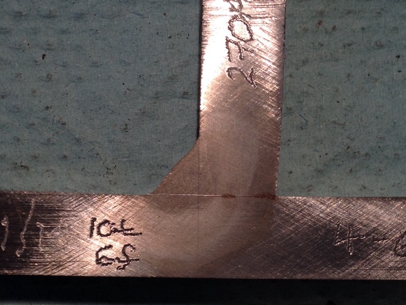
the appearance of the broken welds are presented in
fillet-weld fracture pictures
-
the weld fracture surfaces in this "static" (ie slowly
increasing) overload are apparently ductile "microvoid coalescence"
fracture - judging by the very finely rough grey appearance
-
the observed fracture orientation of the test fillet welds accords
with the observation(s) of the practically experienced
Hicks (ref.)
in his book, see pg82, being along or close to the fillet leg between
weld and the plane of the longitudinal beam surface
-
the deduced value for weld fracture stress does match the established
expectation - but my derivation is different, being simpler and is
based on the observed mode (myself, Hicks
(ref.)) of fracture (developed further imminently)
-
in that the familiar tensile fracture strength of the weld (not
the shear strength, which would be half of the uniaxial tensile
strength) is output by dividing the force upon the weld at moment of
break by {weld-leg-length * weld-linear-length} (the area of the
fractured fillet "leg")
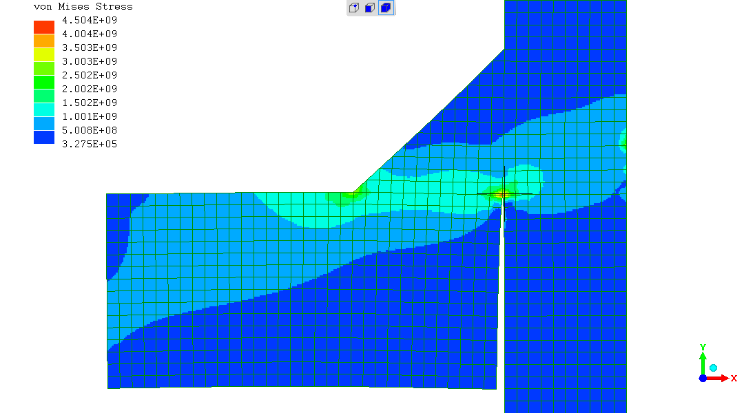
Added on Sunday 07February2021 - FEA of the "bcfwtt":
-
the following two main findings are significantly made by this one
image - FEA output - von Mises stress
which can be identified in the referenced
webpage
on FEA of the "bcfwtt" (stress scale example - "1.001E+09" = 1.001GPa
/ 1001MPa)
-
the location and orientation of weld overload fracture
expected by FEA
concurs with the physical outcome of
own observations and
Hicks (ref.)
-
at the force known in the physical test to cause fracture FEA shows the intensity of stress in the weld appears enough to cause fracture
More detailed interpretation of fillet-weld tensile break measurements
The findings can now be considered in relation to established
knowledge and theory.
Concepts and terminology:
- as I visualise them, from
mp3
- as visualised by Hicks (ref.) on pg85
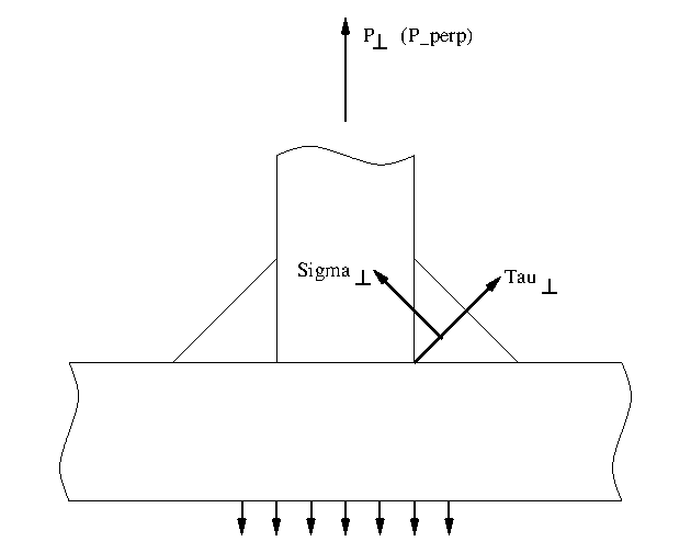
where Sigma=linear-stress and Tau=shear-stress.
Hicks (ref.) on pg85 presents the known
established formula which should connect
strength[MPa]<->force[N]
for a *double-sided* fillet weld
In this equation he presents as [6.3],
with symbols here given text name
P_perp=2.t.L/sqrt2 * (sigma_perp+tau_perp)
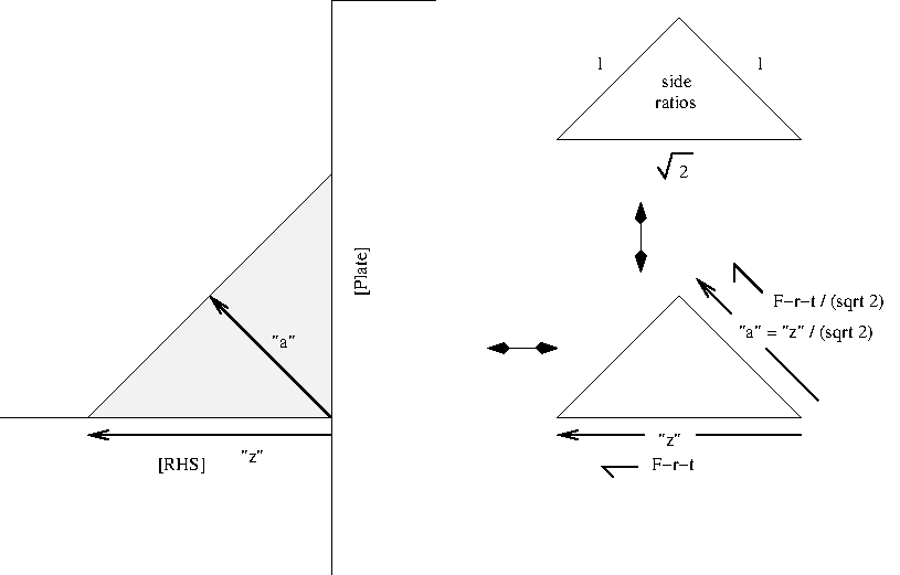
and introducing t=fillet throat thickness ("a" in common welding
terminology) and L=length of the weld
Taking [6.3] and [6.4]
P_perp=2.t.L/sqrt2 * (sigma_perp+tau_perp)
and
sigma_perp = tau_perp {for this geometry}
plus;
we recognise for a 45-45-90 triangular cross section fillet that "t",
the weld throat, which is "a" in conventional weld terminology - that
sqrt2.a=z - the fillet leg-length
so
sigma_perp=P/(2.sqrt2.t.L)=P/(2.z.L)
This is for a *double-sided* fillet weld.
Mine has two welds, but in series, not in parallel.
Each weld must take the full stress - so it is in stress terms a
single-sided fillet weld ("ssfw").
So in my case of applying "Hicks"
sigma_perp_ssfw=P/(z.L)
which is the same as what I found empirically and in forming
mathematics which matches the physical situation. The observation
that fracture is along the longitudinal leg (length "z") of the fillet
weld.
"My" derivation for fillet weld strength and the established
arithmetic expression for fillet weld strength give the same answer.
So, to that extent, my "finding" is "expected".
Whereas the mode of breakage differs, with my derivation expecting
fracture along the longitudinal fillet leg, and the established
expression implying fracture is expected across the weld throat.
Hicks qualitatively comments, on pg82, that fillet weld overload
fracture has the form which I found - close to the longitudinal fillet
leg. So he's derived and presented "the established" analysis in that
knowledge.
So it "doubly" affirms that the derivation applies.
I invite comment on these following things which I find surprising:
-
I know the shear yield is half the observed uniaxial tensile yield -
and you'd expect that to largely carry-over into break-stress - so I
was kind-of expecting a breaking force half of what's observed, given
the argument that this loading looks like pure shear and you'd expect
to see a lower break strength from more "efficient" loading on the
weld metal to induce overload failure ?
-
WRONG !!! -> "why doesn't the "S355" substrate material with nominal
355MPa yield manifest as the strength, given the proximity of the
fracture around the weld-metal||plate-metal boundary?"
-
The 355MPa is the yield stress on distributed-deformation bending - as seen when the beam bends - as observed in own butt-weld tests
mp1
and
mp2
-
Is the break strength of S355 steel in local break constrained to no
distributed deformation 560MPa ?
-
Is the FEA simulation's
(
image
,
webpage
)
full span of weld leg but very narrow high stress zone - about 1.5mm
width at above 1GPa - such constraint against yielding ?
-
Would a "macro" of the break region (section and smooth to fine
abrasive (eg "800 grit") then etch with eg iodine
etchant and examine) show whether the break is through the weld metal
or "parent metal" of the RHS ?
(
example
of a "macro")
"Watch this space.." :-)
References
John Hicks, Welded joint design [3rd-edn.], Abington Publishing, 1999
(R. Smith, 28Jan2021, 29Jan2021 (mp4 str.calc. retn), 31Jan2021 (break tens),
03Feb2021 (560MPa 355MPa), 07Feb2021 (aname, FEA, FEA img preview), 08Feb2021 (aname fea bcfwtt))