This is in-retrospect - the story of an amazing few-day endeavour from
The outcome, what was gained along the way, etc - well, here goes.
As it progressed on through all its phases, it was always a "pilot
study" and "means to learn" or "means to re-familiarise". So I kept
on going regardless and often was reminded of the
song
which includes "... There's three wheels on my wagon, but I'll keep
rolling along. ..."
Yet the outcome was sparklingly good.
I'm sharing something valuable here - the reason this worked so well is I avoided trying to make anything with an intended use. The reason I could keep going regardless. If you "try to get two birds with one stone" - create something with a use and obtain experience - any setback, of which there will be many!, would be a show-stopper...
SHS = Structural Hollow Section.
I have it on word-of-mouth that SHS's really emerged commercially in
the later 1970's (first seen 1960's).
The common experience in "fabco's" (steel fabrication companies) is
that SHS's are gaining ground displacing "sections" (I-beams,
H-columns, angle-irons, U-channels, etc) particularly over the
last couple of decades.
This about "open sections" vs "closed sections" (SHS's).
Why?
This is a complex issue which I have barely described - search online where more explanation and context is needed.
This was the initial entire scope of the project!
Any further "furtive thoughts" were "wishful thinking" then...
I needed to
Backstory - most of my steel fabrications work has been fillet-welding. This in-itself is complex to explain. You get what you get here - else search the Internet...
RHS = Rectangular Hollow Section
Gathered some offcuts of 100x50by8mm RHS in a scrap pan. Actually it is more like I saw the RHS offcuts in a scrap-pan and hatched the idea of this test programme...
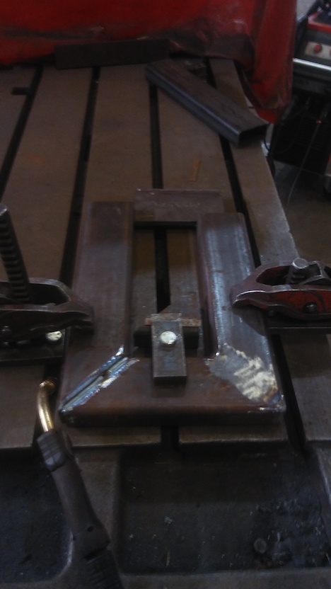
RHS cut 45deg and fitted-up "U". Found great sawing facilities.
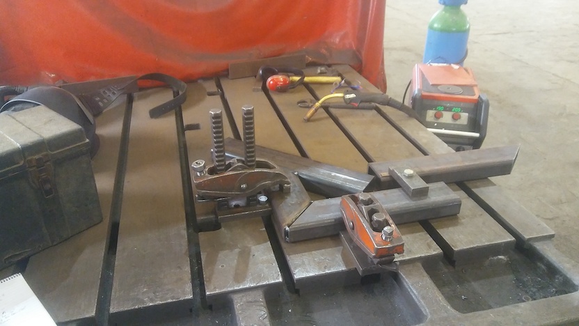
Weld prep. ground 60deg(included) single-V of mitred joint. Clamped and restrained by triangulations for welding. The fab. exercise has me finding great kit. These clamps which fit the stiff level accurate welding bench!
(in background) The welding machine is good. "spray", "dip", thick, thin - all in smooth control.
Welding nearly finished. GMAW / MIG in dip transfer for these 8mm
thickness weldments. Sawed-off a shroud to make a protruding
contactor tip dip-transfer setup for the torch (not obvious in pic.),
to get clean accurate short-stickout dip-transfer welding - another
permanent refinement of technique for work at this place.
Clamps and temporary cross-bracing doing their thing keeping everything flat and distortion-free during welding. Good setup here and feeling enthused.
I did find that, coming from fillet-welding of mainly thick sections
(big steels suctioning heat up 3 paths), butt-welding of much thinner
material of SHS's (2 lean conduction paths so heat slowly
dissipates) presents a very different welding challenge. Good thing
I played this instinct to refine technique.
I found you have to restrain your welding technique and productivity
for metallurgical reasons. You can easily fill the V-groove in two
runs - a root pass then one fill "dammed in place" in the groove it's
filled - but the weld will glow red-hot for double-figures of seconds.
So the strength and toughness to low temperatures certified for the
welding consumable will not be obtained. For properties, you have to
layer-up several crisp lower-Amps dip-transfer runs. Some insight!
Very glad I did this exercise "offline", away from production work.
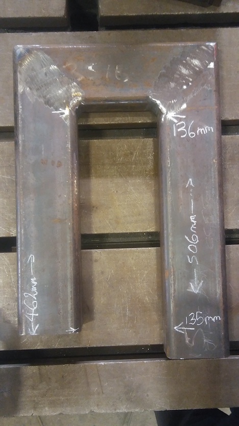
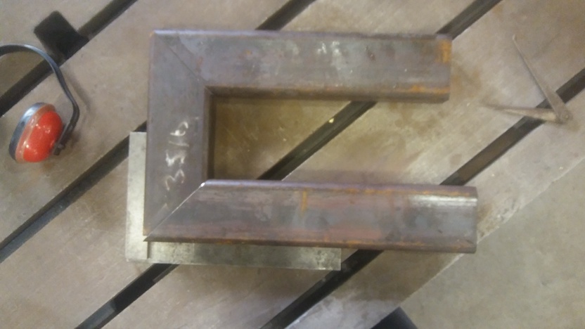
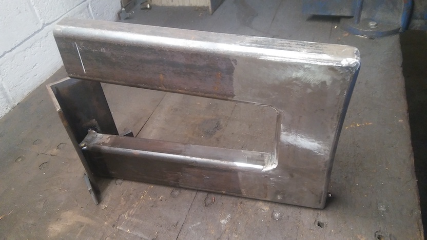
Made it - it's done! Dimensions chalked on. Only 1mm out-of-parallel on 450mm with a lot of stiff welding - which I could remove with a bit of flame-straightening if it mattered but doesn't
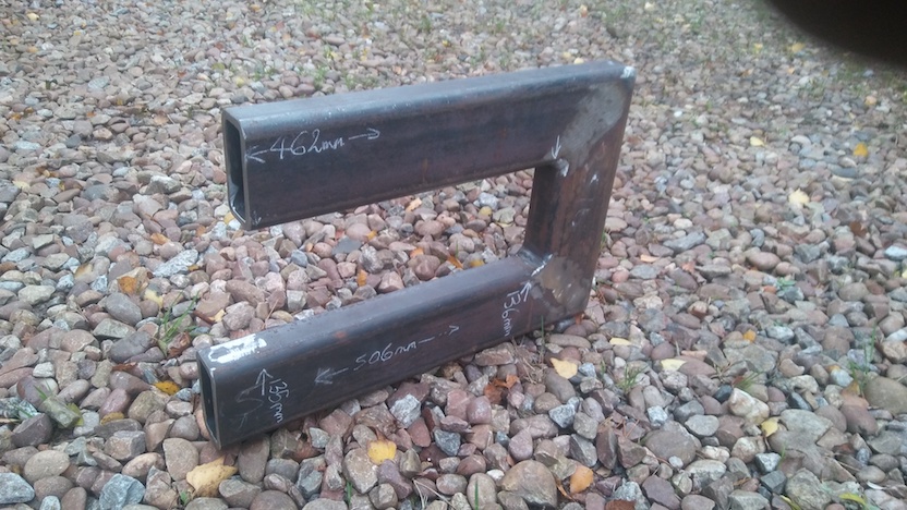
Another view of the created U-frame in Rectangular Hollow Section. This is what I visualised at the outset.
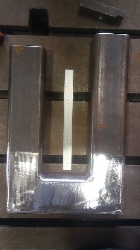
Polishing to "silver". Given...
It no longer looked fanciful about doing mechanical tests on the
U-frame. "Playing the off-chance" I made the fabrication a "U" so
that a hydraulic cylinder could be inserted into the open end of the
"U" to apply a test load. That's a tiny set-up compared to a huge
tensile testing machine for linear "uniaxial tension" weld samples -
some order-of-magnitude well under a millionth in the complexity and
cost.
I was later to find that a much finer finish would be needed.
Linishing only - no grinding with a "hard" wheel.
The rather ambitious hope was to reveal regions of plastic deformation
where the steel exceeds its yield strength in loading - given stress
is in-general not uniformly distributed.
Anyway - there it is - ready - a tentative hope now fulfilled.
In going through the "learning curve", with its various "oooops"'s,
that weld should not be used in the primary pressure circuit of a
nuclear power station, or in a bridge in the Arctic...
That said - let's not prejudge how it will perform in test...
FEA = Finite Element Analysis
The steel weld fabrication stage of the visualised project happened (no show-stopping interruptions; no technical "no go's"). The object which can be tested now exists.
Time to Finite Element Analysis model it. Some long evenings and nights of limited sleep ahead. At least when that happened, the sleep was immediate and very deep, much making-up for hours clipped from sleep time.
We must, of course, honestly look at what actually happens in the programme.
The visualised investigative programme does have some implicit expectations in its design and now is the time to declare them.
There is an expectation that the U-frame in test will bear up to a certain load and spring-back to its original shape - the elastic response region from zero to an elastic-response maximum applied force and hence resultant stresses.
Beyond that "elastic maximum force", the U-frame will permanently deform. With the hydraulic cylinder between the "open" end of the "U", the previously parallel RHS's of the "U" which are about 450mm long are expected to take a divergent splay.
The complexity with this test is, as in the general case, the applied force will result in a complex stress distribution. So the first "overloading" will happen initially in localised regions of higher stress intensity.
FEA predicts the complex resultant stress distribution(s) from an applied load. FEA gives a quantitative link between those predicted local stresses levels and the applied load.Before FEA, this test would be "alright" but tell you nothing quantitative. With FEA, this incredibly cheap test enables a lot of quantitative evaluations.
"My" affordable economically-priced FEA software computer program is
"linear-elastic".
The crucial point is - when the material has yielded, the situation is
no longer "linear-elastic" and the model no longer applies ("works").
But up to the maximum force and stresses of the elastic response
domain it is correct - so you can find that limit which is important
in structural design.
The human deduces that from knowing the material properties when inspecting the stress fields in the graphic virtual object presented in the FEA output.
OK - specifically - I know this steel is "S355", so its nominal yield is 355MPa. Given the FEA is linear-elastic, I apply a trial load, find the highest regional stress, calculate what multiple of that highest current stress is 355MPa, and multiply the applied force by that multiplier to put the virtual object at the point at which it would yield :-)
That is the state you will see imminently in the FEA output presented.
Relating to the real world, a significant approximation is that the
yield stress of the real steel of the RHS will be higher than 355MPa
by some margin. That said, in "modern" steelmaking, certainly in
Western Europe, the control is so fine that the steelmakers can
and do formulate the steel to only just exceed 355MPa - which gives
"lovely" steel which is easy to cut, drill, punch, bend to a defined
radius, etc.
So, again, "we keep rolling along", with all working-out fairly well
in reality.
Behaviour of the U-frame when it is loaded beyond yield is of equally great interest. FEA qualitatively shows where the yielding will start; though as yielding progresses yielding will become more generalised and nothing is predicted about that progression.
How the welds will perform when the object is subjected to gross overload is a prime interest. FEA tells us nothing about that either. Welds which "behave" in gross overload is part of ensuring a "graceful failure" of the structure where the failure in some mishap is calamitous but not catastrophic.
One objective is I haven't done FEA for a while, so this is an
exercise to regain that ability for myself.
An abstract skill like FEA is vastly better learned alongside a
practical context - as is the general case for many of us.
Another objective is to experience the interaction of the FEA and the test of the real object. The FEA being done before the test means it's "out on its own" and has to "sink or swim". Focuses the FEA exercise and adds a sense of excitement. What the FEA shows becomes "a sealed bet" - no criticism, but it's your venture of what you think will happen.
For "sales" and pecuniary reasons, honest information on the ability of particularly computational tools can be sparse. So a simple investigative programme doing exactly what is in the easy range of what these tools do can deliver a rich yield of deep insights into their usefulness. What is valuable which can be done easily; what costs more effort but can be worth it if there is a real need for that information; etc.
The reasons to Finite Element Analysis model is to predict the behaviour in test - the forces, deflections / strain / bending, detailed behaviour expected, etc.
Force and deflection will indicate:
The details of the patterns of stress:
Examples - the predicted force and deflection indicated
First-off - confession - this is in many ways a "dog's dinner"
(ie inelegant).
That said - it gets the job done, and with being a test programme,
once again "... and we keep rolling along".
With it being some years since my last detailed FEA, I had everything
to recall, and I'd forgotten about making use of planes-of-symmetry.
An example is
here
(own web page) where I've only had to model an eighth of the whole
object to make a complete model.
There's some bogus stresses and slightly asymmetric stress
distributions where the inelegance has manifested - but the effect is
negligible. That's to do with where I have had to "hold-down the
model". Implementing planes-of-symmetry, the model would have been
"anchored" on those in a way fully matching reality. Those familiar
with FEA will see it - and if you can't, it doesn't matter anyway.
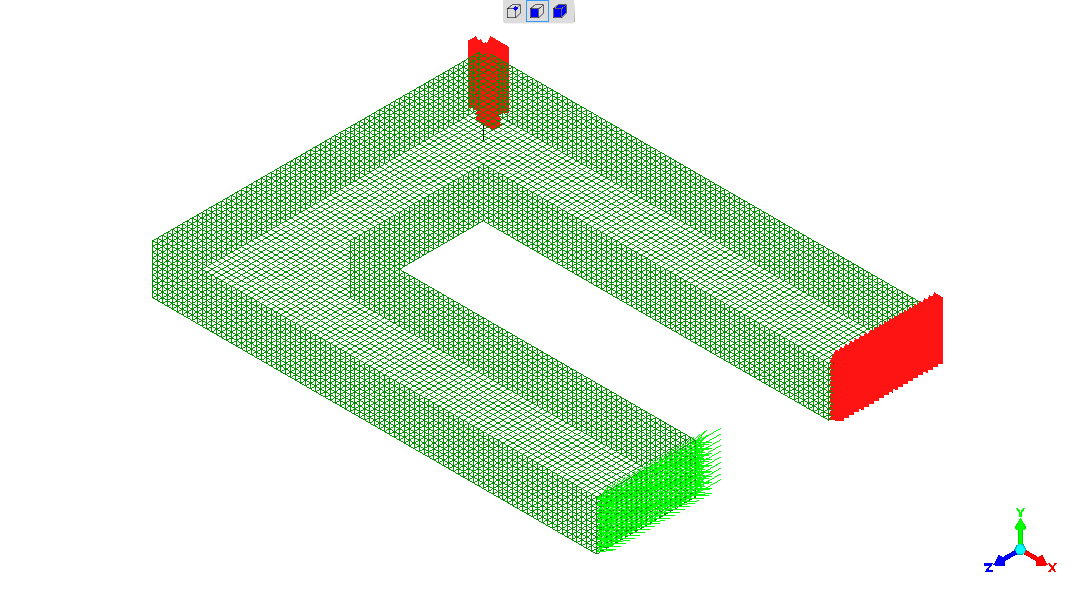
No detailed comment - should have used planes-of-symmetry, with effort going to make a more elegant model. That said - it works.
The dark green lattice is the model representation of the object's
form - the U-frame from RHS.
The "reds" are the constraints - the attachments - the "anchors".
The green arrows are the applied force.
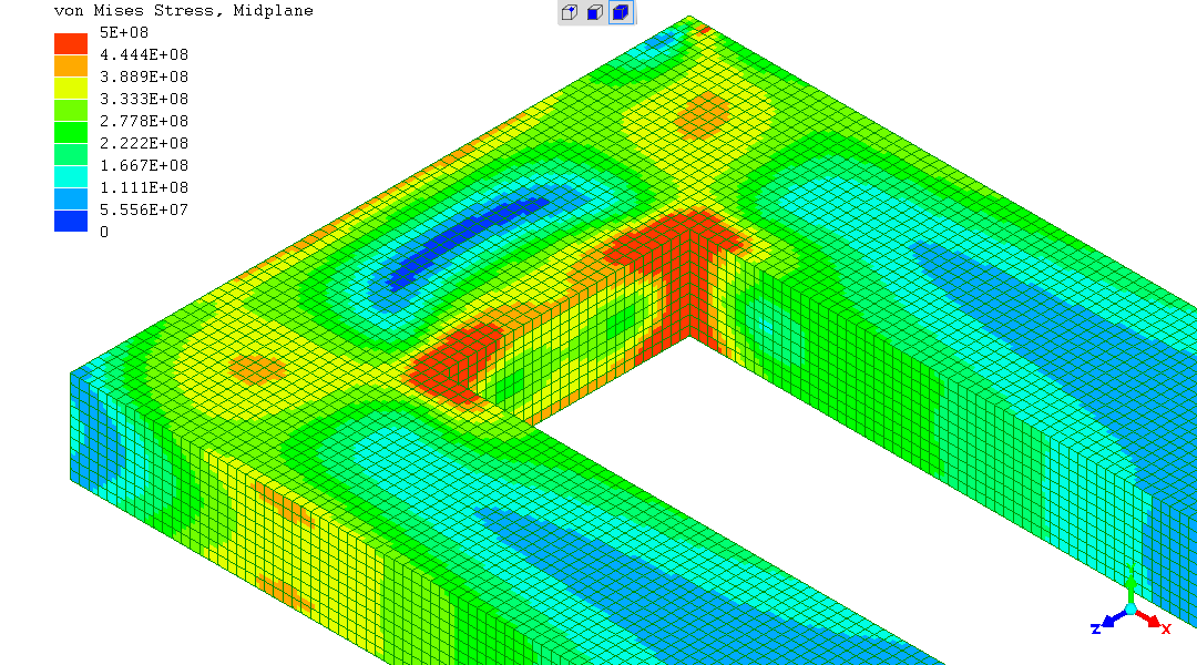
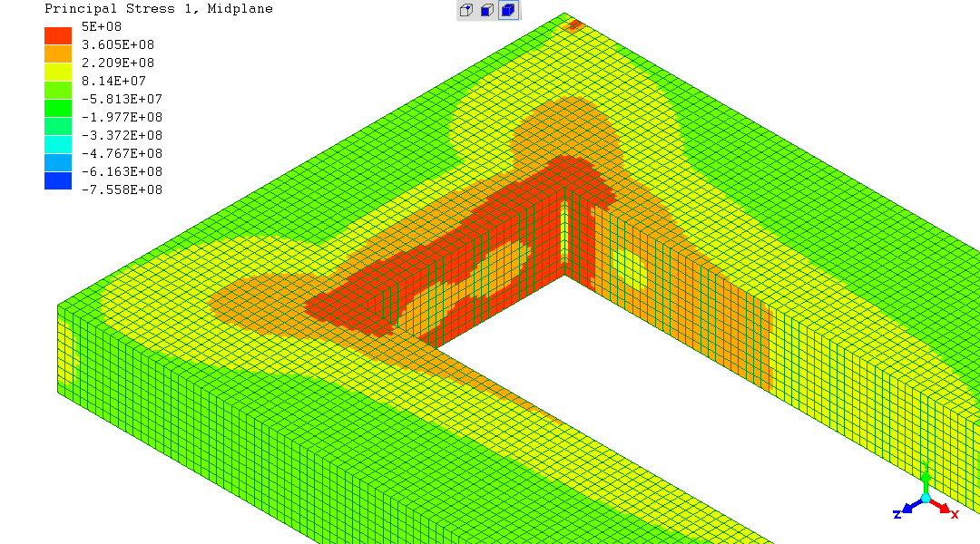
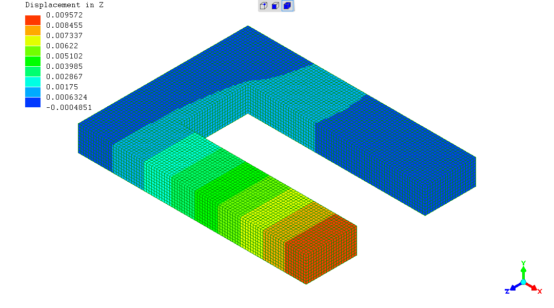
The FEA model output expressed as a graphic of the virtual object colourised to represent the magnitude of the quantity being presented.
This is the "starting" one. von Mises best gives the impression of
when a ductile material (eg a metal) will yield. So I've
deduced the applied force which would send the highest-stressed region
up to 355MPa and applied that.
There are higher stresses in local "hotspots", but I've used judgement
in ignoring those. If they really existed the material would very
locally yield and release those stresses. Then - many are not real
because in the real object, the U-frame, welds fillet the corner and
other corners are rounded, etc.
Next - the Principal Stresses closely agree with the von Mises stress - which would be expected for this case, so is reassuring. All seems well.
The elastic deformation all looks reasonable. All behaving itself, suggesting the model is as-intended.
Going back to von Mises and Principal stresses...
Getting to it - what's the predicted "maximum" load - before onset of plastic deformation ?
It's 66313Newtons (N), applied at 450mm from far "closed" surface of
the "U" shape - right at the open end of the "U" shape.
Converted to something which is probably more familiar - Earth's
gravity is 9.81N/kg, so that's 6~3/4Tonnes-force.
Deformation and elastic expansion at the instant of yielding...
"spot-sampling" on the nodes of the model - the maximum elastic
deflection is 9.5mm.
The prediction is if you measured the U-frame under load, say with a
rule, and stopped when you measure the U-frame is now 9.5mm bigger at
the open end, the U-frame would return to its original shape and
dimensions when at rest.
Go beyond 9.5mm bigger, and you would expect the U-frame would
permanently deform by some amount.
There's a reason for dwelling on this point...
The hydraulic pump and cylinder used have no pressure-gauge.
Pressure would enable a "Force=Pressure*Area" estimate of the force
the hydraulic cylinder is applying, given the diameter of the
hydraulic piston can be easily measured and its area calculated.
There is no other way of measuring or estimating the force.
So deformation and size-change is all that can be measured.
There's high regional stresses along "lobes" down the 45degrees from the corners, across the mitres of the U-frame. Right where the welds are, as it just so happens... So we could expect yielding to start in those regions on the 45degree mitres.
However, the local "hotspot" stresses at the inner base of the "U" are not so "local", so there might simply be plastic bending in beam loading - as if we were talking about a straight beam with no welds...
So the nature of plastic deformation beyond the linear-elastic domain with rising force and stress is not easy to qualitatively predict.
Once again, "the learning curve" hasn't taken anything away for the progression of the programme.
The FEA outcome all looks right in overview, and it's given the crucial exact predictions. We'll have to work with deformations for quantitative evaluation of the actual tests, and we have that prediction of 9.5mm increase in width at the open end of the "U" as the limit beyond which the fully-elastic domain ends and there must be some plastic deformation. We can work with that. So - fantastic really.
Extensive comment is provided against each photo, as the pattern of behaviour observed lead to choices how to proceed with the tests. Given tentative "on the information so far" interpretation of the outcomes and decisions where to go with the next test(s).
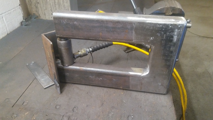
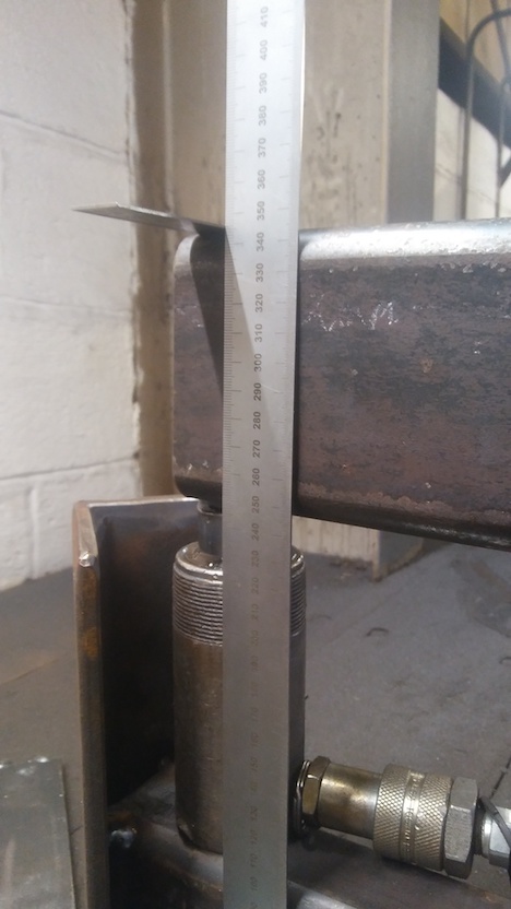
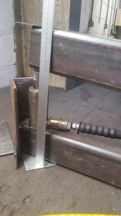
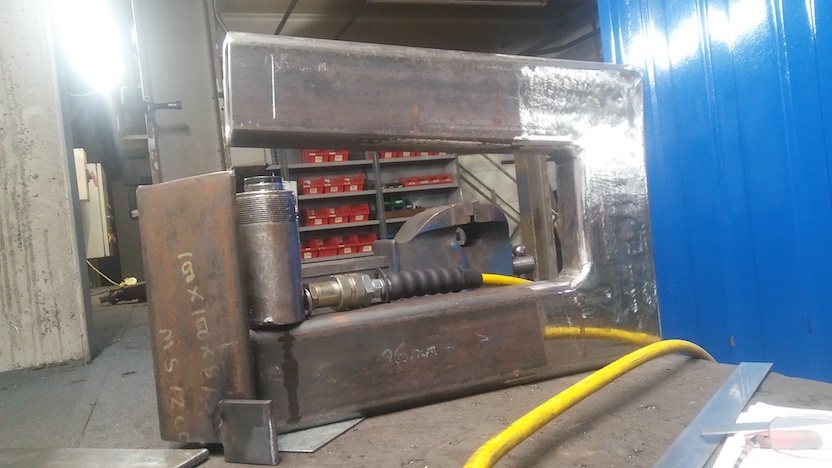
Test set-up "ready to go". Hydraulic cylinder is a perfect fit. Angle-iron added for safety to catch the hydraulic cylinder if ejected by some elastic energy release event seen.
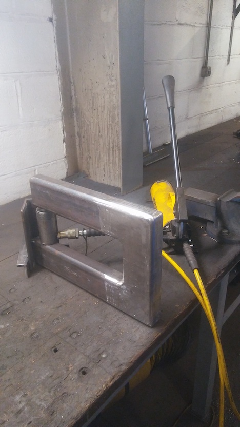
Same - hydraulic pump in-view. Is hand-operated. No pressure gauge, so no "F=P.A" estimate of force, but qualitative impression of force applied to "open-up" the U-frame from force which has to be applied to the handle to pump the piston.
Rule in-place with U-frame at-rest before first ever application of opening-up force. Is 336mm on rule. Opening displacement is relative to this "at rest" measurement.
Getting used to the set-up, there had been some light applications of
a small amount of force then releasing it, and seeing that
measurements could readily be taken. Per prediction; no change in
at-rest size during those "easing-in" pump and release trials.
This was the first application of a force approaching the expected
elastic-domain limit. Rule shows "345mm", which means 9mm of
deflection at the open end of the "U". Returned to prior, original,
rest-state ("336mm" on rule). So, so far, FEA prediction is good.
The U-frame under what must now be significant stress. Nothing to observe.
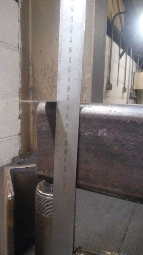
Visible "splaying" of U-frame at "358mm"
There have been previous "pump-up" runs exceeding the +9.5mm
deflection predicted to be the purely-elastic limit, and permanent
deformation had splayed the at-rest state of the U-frame - by a small
amount.
This is the first "pumping-up" run going significantly above the
predicted deflection for extensive permanent deformation. 15mm
deflection noted returns to "348mm" from "358mm" - so 10mm of elastic
strain recovered, with 5mm of permanent plastic deformation. That
15mm of deflection is setting off from "343mm" - already stretched
from "336mm".
Previous "pump-up" runs exceeding the 9.5mm deflection elastic limit
had been by a tiny margin - nothing which could be meaningfully
photographed.
Recounted here is what had been observed before this run going
significantly above the threshold for permanent plastic deformation.
9.5mm of deflection under load had returned to rest-state with no
discernible permanent deflection remaining.
A tiny amount of permanent deformation was indicated at-rest after the
hydraulic cylinder was pumped-up to give "346mm" which is +10mm of
deflection.
So the FEA prediction very exactly predicted the behaviour of the real
U-frame so far.
On releasing the hydraulic pressure, the deformed U-frame is
recovering 10mm of deflection. So the "9.5mm / 10mm" of the FEA
prediction still has some existence in a fairly constant amount of
elastic recovery on load release. The unrecovered permanent plastic
deformation part being the balance - the "pumped-up" deflection minus
10mm.
Which is not unexpected.
Two changes seem to be occuring, from tentative observation and
measurement. Both also not unexpected.
The hydraulic pump is needing more force on the handle to "pump-up".
Plus the amount of elastic recovery seems to be increasing by a tiny
amount after each large-deflection "run".
Two potential mechanisms come to mind to postulate an explanation.
In the first instance of exceeding the "elastic limit", welding
shrinkage stresses could have been released. Very speculative. That
would give a "one-off" invariant change.
Another postulation which seems somewhat likely is that the local
plastic deformation is consuming the softest steel and work-hardening
that steel. That would be a progressively increasing effect with each
"run" which adds to the permanent deformation, increasing both the
force needed on the pump handle to cause the deflection of the
U-frame, and would increase the amount of elastic recovery of the
U-frame - both of which are observed.
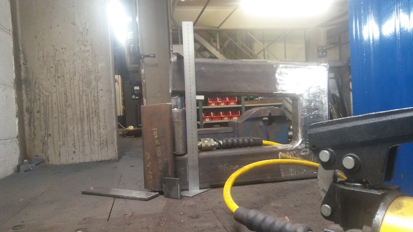
The next run - which was the juncture at which "Stop" was called to
this series of tests on this U-frame.
The deflection measurement is "374mm" on the rule - which needs to be
compared to the original "at rest" "336mm" - so +38mm of total
deflection.
Regarding the hydraulic pump and cylinder, the notably higher pressure
on the pump handle, the inclination of the deflected beam presenting
an off-centre edge loading on the hydraulic-cylinder piston and the
weeping of oil all say - stop! The cylinder is rated at
10Tonnes-force - and it seems probable that that force has been
reached.
So - a desire to keep increasing the force and deformation until
something - on the U-frame! - "gives" / fails / breaks cannot happen
with this set-up.
What has been achieved and obtained in this programme of activities and investigations up to this point is amazing.
Here are a few more pictures showing the state of the U-frame on completion of the testing programme.
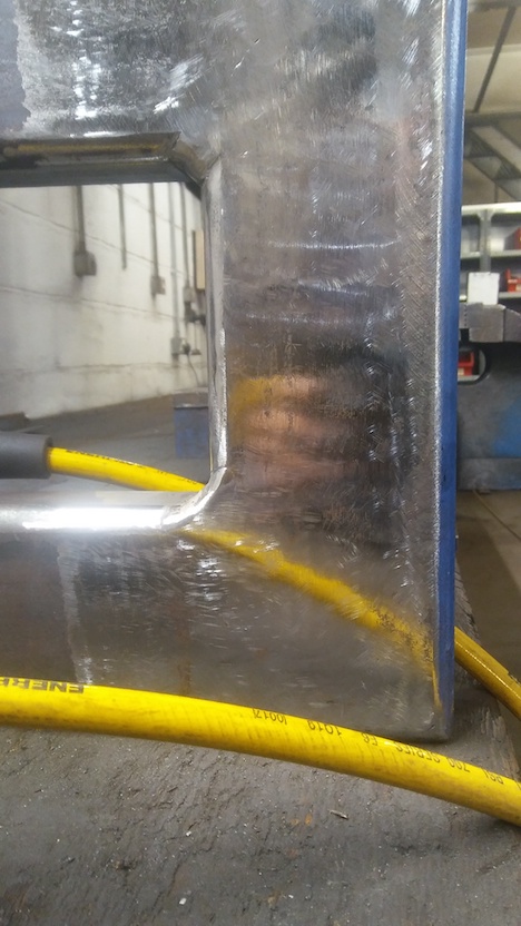
Obvious permanent plastic deformation.
This view indicates that the yielding and deformation could be uniform "rotation" along the "closing" face of the "U" shape.
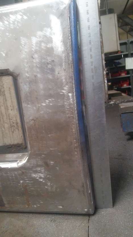
That impression is supported. The rule (straight) supports the impression of a fairly uniform radius of curvature.
In these images of the U-frame at the ending of this test programme, no observations seem available to make on the (insufficiently) polished side-faces of the U-frame.
Flawless behaviour of the structure to significant deformation.
Again, inspite of awareness of "the learning curve" and shortcoming in
this test object, the welds performed flawlessly, never revealing
their presence in any way. FEA would indicate that the welds are in a
higher-stress region radiating outwards on the 45degree angle from the
inner corners of the "U". So they should be being tested here, for
sure.
Lots of speculation, tentative interpretation and postulation - but -
overall - indications are good.
The other thing is - how remarkably closely the FEA model simulation results matched the outcome for the real steel-fabrication U-frame tests.
Finally; seeing the deformed U-frame with the "closing" face of the "U" shape in a smooth curve reminds of beam in overload behaviour where than beam has "plastic" behaviour. Which these RHS's do have. As if the behaviour of the U-frame is dominated by the section behaviour and not welds and corners behaviour. Begging the thought for an extension of the investigative programme in treating the U-frame approximated as a straight beam using the Euler-Bernoulli beam formulae.
Euler-Bernoulli beam theory, derived about 1750, is useful for many /
most beam applications. The beam must be long in relation to its
section for the theory's simplifications to have negligible effect.
Which is generally the case for common beam applications, and is so in
this case.
Euler-Bernoulli beam calculations are very useful.
The stages of the calculation are worked-through.
My apologies that the explanations and workings are brief.
There are a lot of resources on the Web about beam theory.
No derivation - simply use the formula I=bh^3/12 for a solid rectangle bent about the middle. b-breadth; h=height.
For Second Moment of Area, it is permissible to subtract, so the Second Moment of Area of a hollow rectangular section can be obtained by subtracting the Second Moment of Area of a rectangle the size of the hollow from the Second Moment of Area for a solid rectangle with dimensions the same as the outer dimensions of the RHS.
The wall thickness is 7.8mm - the value used in the FEA computations.
I_outer=50e-3*(100e-3)^3/12 = 4.1667e-6m^4
I_inner=34.4e-3*(84.4e-3)^3/12 = 1.7234e-6m^4
I_outer-I_inner=(4.1667e-6)-(1.7234e-6) = 2.4432e-6m^4
So; I=2.4432e-6m^4 for this 100x50by7.8 RHS
A beam's ability to bear load can be rated by a single unique value - its ability to bear a Moment (twist). With value in N.m
For a symmetrical section, which an RHS is
M_max=2.sigma_max.I/d
Where sigma_max is the limit of the ability of the material to bear
tensile load - commonly the yield stress, and d is the depth of the
section. I is the Second Moment of Area - previously mentioned.
Therefore
M_max=2*355e6*I/100e-3 = 17347Nm
The well-known "Blue Book" has a value for a 100x50x8mm RHS of 21800Nm.
By my calculation for a thickness of exactly 8mm, my obtained value is
17660Nm - which does not agree with the "Blue Book" - explanation
unknown.
It is now necessary to identify the beam situation for which there is a known answer.
This is how I attributed a length to the "beam":
ie the length along the middle of the RHS U-frame.
So the beam length is
2*(450-50)+(355-2*50)=2*400+255=1055mm
The beam situation is equivalent to two simple cantilever beams of half this length back-to-back - butting at the plane-of-symmetry halfway along the closing face of the "U" - at the "U"'s long centreline.
The "cantilever half-beam" is therefore 527.5mm (527.5e-3m) long
We already know the Moment Capacity of the RHS is 17347Nm, so its
load-bearing capacity as a simple cantilever beam is
17347/0.5275=32885N
In this visualisation, each half-beam supports this load, so the total
is 65770N, which is 6.71Tonnes-force. Which very closely matches the
FEA prediction for the U-frame.
The load-bearing ability of 32885N for the "cantilever half-beam"
feeds into the Euler-Bernoulli formula for deflection of a single
cantilever beam
(load*length^3)/(3*elastic-modulus*I)
=32885*(0.5275^3)/(3*2e11*2.4432e-6)
= 0.003292m
= 3.3mm
Both "half single cantilever beams" deflect, so the total deflection
at maximum load before onset of yielding is 2*3.3=6.6mm
That is fairly close to the FEA prediction of 9.5mm, which the physical U-frame load tests supported by the very close correlation of real and predicted values.
It is postulated that the mitred corners add some more flexibility /
reduce stiffness in accounting for the extra deflection of the U-frame
compared to a straight beam of the same length from the same
100x50x7.8mm-thickness RHS.
That
So the final image presented from the load tests on the actual
U-frame, showing a smooth deformed curvature, is strongly believed to
correctly hint at the dominant nature of the response to the forces
applied being simple beam behaviour.
For this programme of investigation, that is great. It means that it
is as if the welds were not there. That is - the welds perform
perfectly. Good !
A lot has happened in this short time of 9 days in total.
All the very different aspects of the investigative programme happened
in those days.
There seems to be a rich harvest of successes in those days of focused
endeavour.
(R. Smith, 20Nov2020, 21Nov2020, 22Nov2020)