Tensile-test rig for beam-configuration fillet-weld samples
What it does; the requirement it fulfills
This tensile-testing rig can by design repeatedly take the "brutal"
abrupt release of stored elastic energy from break at maximum load,
which the "beam-configuration fillet-weld sample test" inflicts.
While providing accurate determination of the tensile force in the
sample fillet weld at that breakage.
The sample does not possess a concept of yielding : yielding
behaviour; yield point; yield stress. The only significant event with
increasing force on the weld is its abrupt breakage. Hence - the test
method in measuring the maximum force attained at the moment of weld
breakage measures the only tensile characteristic the fillet-weld
sample has.
The goal attained
The beam-configuration fillet-weld sample test presents a previously
unfamiliar vision, that complete fillet welds can be easily and
economically tested to unrestricted sizes of fillet weld.
A further vision for the future is that this test could be developed
into a dynamic-load / cyclic-load test for fatigue-resistance of
fillet welds. There being no foreseeable fundamental impediment
currently to that goal.
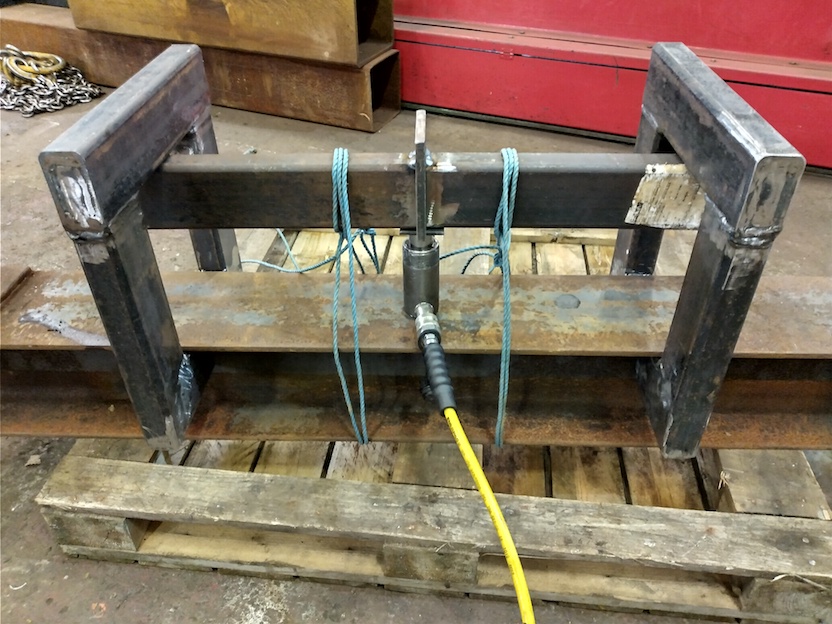
The test rig presented
This is it - picture of the test rig produced and found good in trial
tests:
First and foremost - keep distant from the test sample as load is
increasing !!!
The typical 2 metres or more length of the hydraulic hose pulled
straight away from the breaking rig to the hydraulic hand-pump is a
good start.
On breaking, the sample halves "leap" spectacularly. So you need to
keep well clear. Well outside the envelope of space within which
those ropes restrain the sample parts to stay.
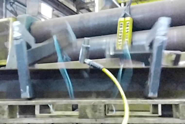
Impression of the test completion event is given in following image,
indicating
-
the advisability of persons keeping distance from test when increasing
and/or high load
-
the need for this rig, designed to be tough, durable and retaining
force measurement accuracy, when every use has abrupt sample break at
maximum load attained
Onwards...
-
the "frame" is piece of beam - no alterations needed - which is not
affected by being used in this test (you can use any beam which
happens to be present)
-
the "mechanism", which is hydraulic, is a standard kit, a hand-pump
connected by hose to a cylinder ("jack") - an "over-the-counter"
combination sold for many miscellaneous purposes.
-
a pressure-gauge on the pump-and-cylinder set gives an accurate
"F=P.A" (Force=Pressure*Area (of the cylinder's piston)) estimate of
the force the cylinder is applying to the middle of the test sample
-
none of the hydraulic equipment is vulnerable to repeated abrupt load
release
-
if there is a pump-and-jack with pressure-gauge available for general
use, the only test equipment specific to the test are the two "end
hoops"...
The ropes binding the sample and "frame beam" are safety-critical and
are integral to the design of the test method.
They are vital for the safe application of the test.
They constrain the sample halves to remain within a small envelope of
space on sample breakage.
The following detailed comment is impressed upon readers as being
important to know already, or to skill-acquire to mentor-approved
competence.
-
the fibre rope restrains the halves of the sample on breakage,
preventing the stored elastic energy at breakage projecting the halves
distant at high velocity - common "blue, disposable" cut-film
polypropylene 3-strand laid rope being recommended
-
*** it is important that at least one of the turns of the rope grips
the sample, typically with a clove-hitch - so the halves cannot escape
the restraint of the rope
-
10mm rope would be recommended - thick enough to have enormous
strength (ISO Standard for 10mm 3-strand cut-film polypropylene rope
is 1.3Tonnes-force minimum break, and you have two or four "falls" of
the rope) - yet pliable enough to tightly form a gripping knot
with eg a clove hitch (the rope seen is 6mm - higher
safety-margins recommended)
-
*** general but important advice - to join the rope back on itself to
form the turns around the "frame" beam and sample, you must not use a
"reef knot" or even worse, the "shoelace knot" ("granny knot") -
typical easy suitable knot is a "sheet bend"
-
*** fibre rope will withstand big high-rate shock loadings and
dissipate energy - particular reason to recommend common polypropylene
3-strand rope, not "high-spec" cordage like nylon braid - so consider
carefully the suitability of any alternate plans to restrain the
sample halves on break
Other comment:
-
the height of the two "end hoops" is restricted to just enough to get
the intended beam size and cylinder into the rig - making it
inherently difficult for anyone to unwittingly grossly overload the
rig
-
hydraulic hand-pumps *usually* have a pressure-relief valve,
activating at 700Bar (about 70MPa) pressure, which enables the
cylinder to freely reach its rated force capacity - but not exceed it
-
if the fillet weld size were excessively increased, the event which
would intervene is that test-beam would begin distributed plastic
bending - on reaching the Euler-Bernoulli beam formula predicted load
for onset of plastic deformation - which is a gracefully progressive
failure
-
with the common "S355" steel grade Rectangular Hollow Section (RHS)
forming the test-beams (nominally 355MPa yield strength), and common
"70-grade" weld metal eg GMAW / MIG "G3Si1" (US "ER70s-6") weld
metal with typically 560MPa break-strength, for a weld just less than
the RHS wall thickness (eg a 6mm leg-length weld on 8mm wall
thickness RHS), the weld will break at only a small margin beneath the
no-yielding strength of the test-sample half-beams
-
overall - there seem to be interlocking inherent characteristics of
the test-method which make it fairly well-behaved and difficult to
systematically abuse - BUT if you you have technical knowledge which
indicates the test could have "unstable" behaviours or could enable it
to do unfortunate things in normal operation or if abused - let me
know...
Interpreting the test data - obtained weld break force from rig piston-force
Technically - the objective of the test...
Deduce, from the hydraulic-cylinder piston-force at the moment sample
broke, the tensile force on the weld at that moment. Which might then
be used to deduce stress levels in the weld at that moment.
-
the hydraulic piston force would usually be obtained as an "F=P.A"
estimate from the hydraulic fluid gauge pressure (P) and the area of
the piston (A) - familiarly A=Pi.d^2/4 where "d" is the known piston
diameter - thus F=Pi.P.d^2/4
-
the analysis which derives the weld force and stress from the
hydraulic piston force is presented in article
"Fillet welds tensile tested in beam test",
section
Stresses in weld analysed
,
to which I refer you for that derivation
-
the text line
"F_w=-F_p*L_m-a/2h"
is the crucial derivation - where force in the weld is F_w, and
"L_m-a/2h" is a dimensionless ratio of the length between
central-plate and end-hoop, to the depth (height) of the RHS
beam-sample half-beams - with the "1/2" included to account for two
welds sharing the reaction to the piston force.
-
the sample has two welds forming the load-bearing path from the
half-beams through the central plate, and if identical, either of
these could break - so be mindful of any statistical or other
consequences of "the weaker one of two welds" being found in a typical
test
-
the
derivation
also shows plausible deductions of stress acting in the weld-metal
which will ultimately cause it to fracture in overstress, with rising
applied test force
Weld-metal break-strength from the trial fillet-weld beam-test
This is an example "working" of the arithmetic process. One would
hope in future for more exact and citable input data.
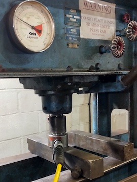
The hydraulic hand-pump and cylinder has no pressure gauge. However,
the cylinder can be put in the "shop" press seen in
Fillet welds tensile tested in beam test
, where the force this hydraulic cylinder applies to the
shop-press's ram causes a force reading on the press's gauge
(
example - image
)
.
Giving an approximate semi-quantitative "calibration" of the force
exerted on the pump handle to the piston force resulting. (!! - yes,
this would normally seem "inexact methodology")
With no way to readily predict the deduced value of stress in the weld
at break, there is no way to bias the estimate of force from pumping
the handle in order to get a preferred value. I estimated
8Tonnes-force at the breaking for the sample seen in the picture.
-
force applied by the piston, "F_p", is estimated as being
8Tonnes-force
-
"L_m-a/2h" = 350/(2*100) = 1.75
-
thus, force across the weld = 8*1.75 = 14Tonnes-force
-
convert to Newtons, N, given 1000kg/Tonne and gravity=9.81N/kg, so
14*1000*9.81=137340N
-
the area of the fillet weld leg fracture surface is
leg-length*weld-length (6x40=240mm^2), which converted in m^2 is
2.4e-4m^2
-
apparent breaking stress in Pa (1Pa=1N/m^2) is Force/Area, which is
137340(N)/2.4e-4(m^2), giving answer 572MPa.
Where the closeness of this 572MPa estimate of "G3Si1" breaking stress
to the "expected" value of 560MPa is truly remarkable and surprising.
Evaluation of fillet-weld beam-test samples - see
This is an article on the beam-configuration fillet-weld tensile test,
the testing method.
For interpretation and evaluation of fillet-weld performance, see the
page on
Fillet-weld test evaluation
.
Where this test outcome data is incorporated in the body of data and
observations available - both my findings and established knowledge.
Recommendations for further work
A pressure-gauge on the pump giving a reading of the hydraulic
pressure in the system would be very much recommended ;-)
(R. Smith, 24Jan2021, 26Jan2021 (edits, fractpg), 28Jan2021 (findings
sep.), 28Jan2021 (break img.), 29Jan2021 (approx brk.str. retn),
31Jan2021 (break tensile, no yield, edits), 07Feb2021 (aname
fwanalyse, F_w, pic cyl test), 08Feb2021 (pic cyl test), 11Feb2021 (dir img))