A very cheap test of fillet welds was recently developed. Enabling
the extensive testing necessary to use a prior observation that, with
correct welding conditions, the fatigue performance of fillet welds
can match the fatigue performance of the steel plate and sections it
is joining. Enabling welded steel structure as a whole to have an
unfamiliarly excellent performance in cyclic-load applications like
bridges.
The only plausible visualised explanation for the novel high fatigue
endurance would imply that fatigue performance will increase with the
increase in quality and strength of the plate steels used. Presenting
the vision that very high performance bridges and other fatigue-loaded
structures could make full use of higher yield strength steels like
the 690MPa, 960MPa and 1100MPa TMCP plate steels.
The new fillet weld test, in combination with basic investigative
techniques like metallography, can check the validity of the apparent
new principles, and if confirmed, can provide the data to inspect how
many more beneficial weldment behaviours are found. If that proceeds
favourably, the tests can then be used in optimising detailed
engineering design in the application of high performing steels.
I am writing at the start of 2021, given unexpected developments in November and December 2020.
Those unexpected developments provide the "missing link" on the path to the very desirable goal, which can now be reconsidered.
The focus on fillet welds [definition] is because
Applying high-strength structural steels, eg 690MPa TMCP steels, bearing high cyclic stresses in proportion to that strength, in welded steel structures - the initial aim being bridges.
Historically derived axioms about weld behaviour so limit acceptable service stresses in dynamically loaded structures (eg ships, bridges) that there is no advantage in going above the 355MPa yield strength of the common "S355" grade.
Frustratingly meaning that, by these rules, high-grade structural steels offering both strength and toughness offer no benefit in bridges and other fatigue-loaded welded structures.
That is what we want to progress beyond. By adopting a new set of rules if proven correct by this programme. Which do assign benefit to applying high-grade high-strength steels.
I am interested in conducting this work, from necessary preliminary "confirmation" tests, through development of the necessary portfolio of detail knowledge, to implementation in structures in service.
In two "passes" :
The surprise, unexpected, finding in late November 2020...
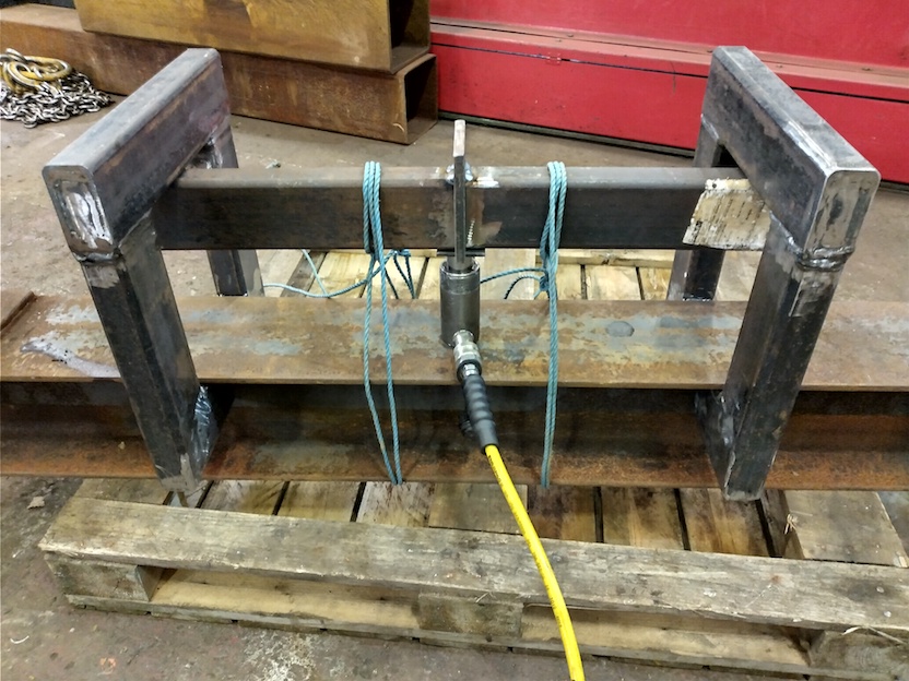
A "beam configuration" strength test of full-sized fillet welds, as
follows:
[update : same
test sample
,
in purpose-built
testing rig
of mid-Jan2021]
(where the fillet size of a "cruciform" tensile sample is severely restricted - maximum about "z10" (10mm leg-length) for a "big" 100Tonnes-force tensile testing machine if aiming for 690MPa yield steel)
This test seen is "static" for tensile strength.
The leap-of-faith is:
there is no obvious impediment to making the beam configuration fillet
weld test "dynamic" for fatigue strength.
What seems to have presented itself is (sequential points) :
This is a necessary capability enabling progress, where that had been previous infeasible.
The need for a test of fillet weld fatigue performance does not stop at identifying the overall technical strategies to get high-performing welds.
Across the design of the structure there is need for a "case by case basis" ready economical test for fillet welds because
In an investigation 10 years ago, I found that fillet welds "as welded" with correct conditions by MIG/GMAW (#135) and FCAW (#136) - both rapid economic "workshop" / "factory" welding processes used manually and robotically - can have a "crack incubation period" many times the "crack growth to failure" period.
Specifically...
The "my specification" FCAW T-fillet fatigue test sample ran to 1.4Million cycles unbroken with no detectable cracks yet formed, when every similar sample welded to the WPS (Welding Procedure Specification) failed at the predicted 250Thousand cycles (all samples broke between 200K and 300K cycles).That "optimised" welding condition is what a welder in a general constructional steel fabrications workshop ("mainstream EXC2") on any typical industrial estate would use if they had to trust their life on that weld at-site as the steel-erector (North American : "ironworker"). The nub of the issue is weld-pool fluidity.
The significance of that result can be seen in the presentation of the data as an "S-N curve" plot.
The "my specification" weld is seen as the "DH36FCW" purple square just under the "Class B" line at just left of "N=1.6e+06" horizontally and just under "S=200" vertically - with its red arrow slanting upward-right denoting it as a sample which had not broken.
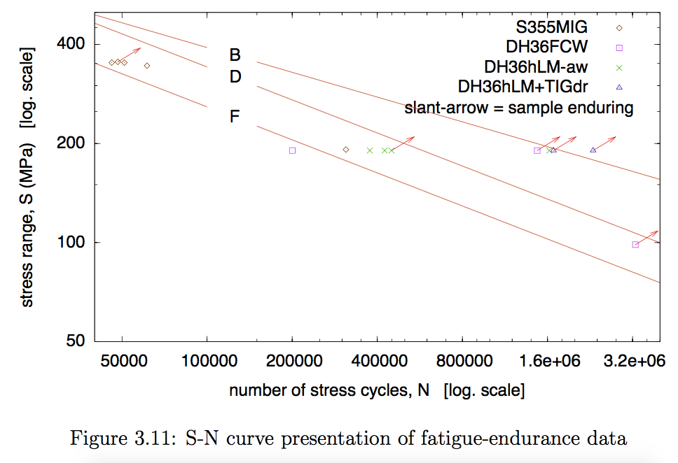
That "my specification" FCAW weld remains unbroken at 5.9 times the "Class F" predicted endurance to break for such a fillet weld.
The other results in that cluster are "special" laser+MIG hybrid
research welds; the unbroken ones having post-weld TIG dressing of the
weld external profile; ie a supreme specification.
"Class B" is the rated fatigue endurance of as-hot-rolled steel plate
and sections...
The meaning is that fillet weld fatigue resistance has converged up to
the fatigue resistance of the steel plate it is joining.
Across published metal fatigue research, when weld fatigue resistances
get to around this level, some fatigue failures occur in the "stock"
part of the sample away from the weld.
The "Class D" line is the rating for a co-planar butt-weld of high quality.
The other "DH36FCW" purple square for the comparable test, but with the sample welded according to the WPS, is found just under the "Class F" line. Which is the historically expected performance of a fillet weld, where it broke at "N=200000".
The one MIG weld sample with comparable test is seen as the brown diamond-shaped data-point nearby, just above the "Class F" line. So has similar fatigue endurance.
It has already been identified that the "my specification" weld is
showing a fatigue performance similar to that of the plate steel it is
joining.
That, in itself, could be harnessed to very useful effect.
The ramifications could go a lot further, and beg investigation.
The only plausible explanation for the combination of
That contradicts founding axioms, express or implicit, feeding upward and tangling into the detail rules of current design Codes as they specify the engineering of structural steelwork.
For the overall structure of knowledge and understanding of fatigue cracking, I delegate to the "Wikipedia" page on Fatigue (material) . Where early section Stages of fatigue has subsections Crack initiation and Crack growth .
The fundamental "key" axiom about weld performance in fatigue loading, which for steel structure
To indicate what is meant by a "fatigue-resistant" weld - it is suspected that these two welds - both solid-wire MIG (#135), example 1 and example 2 , might be highly fatigue resistant.
If a weldment's fatigue life possesses a significant "crack incubation phase", the fatigue performance must become a function of the steel's yield strength. In that, in an otherwise good steel with a higher yield stress, the accumulated cyclic loading severity to crack incubation should be higher / longer.
In essence, the question is - regarding fatigue performance, can weldments with the right welds take a likeness to forged-and-machined machine components?
The obvious and necessary question is - does any other characteristic of a weld defeat the promise that higher yield steel "must" lengthen the crack incubation period?
Given potential global economic benefits of gargantuan proportions, these are fascinating questions of pressing significance.
With the direction of attention being - can there now be effective application in bridges and like cyclically loaded structures of higher-strength steels, particularly the low-temperature-tough TMCP steels in grades like 690MPa-yield, 960MPa-yield and even 1100MPa-yield?
What we do already know from the "my specification" weld sample is that welded structures with currently applied materials, but with good attention to smoothing details and eliminating chronic stress-raisers, could operate at a significantly higher cyclic loadings. Approaching the limit dictated by the structural "mill" steel itself. That would be a 2.2-times increase in the cyclic stress range permissible (explanation) - extremely beneficial.
What we absolutely do not know from my finding(s) is what happens to fatigue performance of welds made to this strategy, as higher strength steels are used with at-least strength-matching welds, and the fatigue stresses are increased in proportion, to use that strength.
Therein lies the big next question...
Current computer/electronic-controlled eddy-current methods of
Non-Destructive Examination can verify that welds have the
high-performance characteristic.
The method is rapid, enabling 100% inspection for guarantee of
in-service performance.
This transforms the readiness with which the test programme and the
commercialisation of the high-performance steel structures can be
achieved.
Because we are considering fillet welds, Finite Element Analysis (FEA) modelling is transformatively useful. Where many coplanar butt welds can be approximated by "Stress=Force/Area" arithmetic. But not any other geometry of butt weld...
FEA modelling is generally available now, readily applied and very useful. On a pragmatic level - "linear-elastic" FEA of structures is abundantly useful and "computer programs" implementing it are very economical.
In every other case for structures than uniaxial tension (?), there is a "contour", a spectrum, of stresses non-uniformly distributed as they "flow" through the load-bearing structure. Which is is necessary to analyse to optimise design.
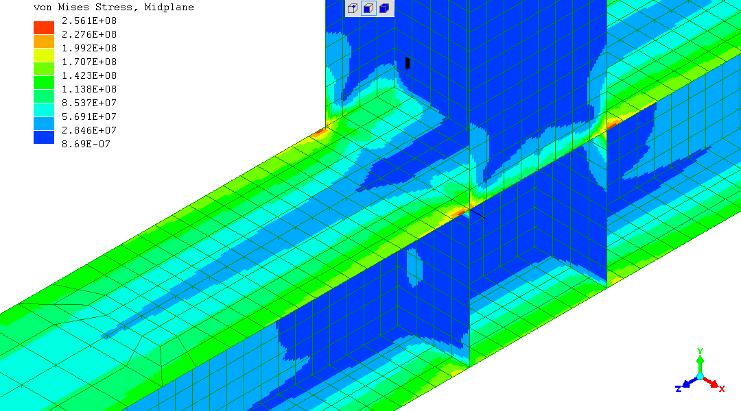
To illustrate - here is
my own example of FEA
analysing the effect of weld toe geometry.
This is an analysis of a very detailed matter.
The "beam", "column" and other arithmetic equations reveal proportionalities and will tend to be use to define the overall design. Which will give the input values to the next application of FEA illustrated.
FEA will quantify and present regional stresses, showing the flow and
concentration of stress across regions like intersections forming
joints.
This is not a particularly good example but is illustrative -
one image
.
See shortly - FEA modelling is used to analyse the beam-configuration fillet-weld tensile test and its relation to commercial structural welds.
Recently offered commercially, "S460 grade" / 460MPa-yield hollow sections - square and rectangular - may prove a welcome bonus in the testing programme. In forming the substrate material for the beam-configuration fillet weld tests, as the effects of increasing the strength of steel sections and welds is investigated.
During the Christmas holiday period of 2020/2021, I managed to read some recent engineering analysis "papers" on applying high strength steels in fatigue-loading applications - particularly bridges.
I will provide the detail of how the assertions in my "overview" presentation just completed is justified.
You may choose to jump ahead to see how my work and findings relates to recent engineer thoughts.
That's right. As both a welder and an engineer I am able to tell you
that's the case. Technically, it is now easy to make welds with high
fatigue performance.
Human political interactions, in the form of disputes, are the sole
reason why welds are shunted consistently onto a poor performance.
Farcical "bun fights" between organisations, about the fulcrum of
rule-sets which no-one in "managerial" positions has the overview to
see have become outmoded.
Welders (the persons) respond by running their welds colder to conform
to ill-judged style orthodoxies.
See the detailed arguments about welding, welding methods and welding
technique.
Important reality to always know
Presented in my webpage:
New additions in February 2021 on using the method:On the matter of costs and understanding why the opportunity which seems so attractive now has not been "covered" before:
If the minimum length of a weld is 10 times the leg-length
(to guarantee what is being tested is the properties of the weld, not
the property of the sample's ends)
then for a 30mm leg-length fillet the weld would need to be 300mm long.
That would have a breaking force of about 5MN - about 514
Tonnes-force.
To balance a uniaxial sample, it would have to be a "cruciform"
configuration test, with two fillet welds balancing about a central
axis. That makes no difference, because the stress we are considering
is in the section - which we can take as 30mm*300mm.
For S355 steel, we need 325 tonnes-force to reach yield.
Clear the way to put 690MPa steel to yield stress, that's 633
Tonnes-force.
Fast fatigue test at 600 Tonnes force is enough, so there you have it,
a 600 Tonne-force uniaxial fatigue-testing machine. No such machine
exists (?), and would be enormous.
Then there would be the cost of its use.
10^8 cycles is where we typically might want to know about bridge endurance.
Suppose this machine could do 10 cycles per second (1 cycle per second
is typical for a 100 Tonne machine) then each test would need 116
days.
If it were in the form of a "Vibrophore" resonant fatigue testing
machine running at 10 times that rate, that's still over 10 days.
You are not going to have several of these machines, to speed-up the
data acquisition.
The beam-configuration test would need a 200Tonnes-force hydraulic
cylinder with a 50mm stroke - which can be bought "over the counter"
from a rigging and lifting equipment supplier.
Its "pump" would be novel but achievable - probably a reciprocating
pump with no valves, where the "pump" and the "cylinder" move in-step.
With a flywheel with enough stored energy that the driving motor only
has to make up for friction losses.
A 50Hz test rate might be achievable, using a 3000rpm electric motor.
Take a 1500rpm motor, for 25Hz testing rate.
This testing setup occupying testing equipment costing a
US$-a-few-thousand equivalent would complete this "monster" test in
about 50 days.
I'd recommend putting two beam-samples end-connected with plates back-to-back, so there is no supporting structure and one test is testing 1.2m of weld ((2*300mm)*2).
The set-up is no bigger than the sample - which would be about 4m long - so there could be many of these tests running concurrently. Probably in an outside yard area, not using up prime laboratory space. Else in a "low cost" warehouse building.
That's with seeing the way to "headroom" for testing 30mm leg-length fillets on 690MPa yield steel, which was previously inconceivable.
Uniaxial tension fatigue testing machines are often servo-hydraulic with computer control to give the stress cycle desired. Expensive and power consuming - typically 10's of kW at the hydraulic drive pump.
This is not envisaged with the beam-configuration fillet-weld fatigue test. A "simple" mechanical-hydraulic system is envisaged. With all variables adjusted at the outset. How so?
The beam-configuration fillet-weld test can be "tuned" by ready adjustments like moving its support bearers closer together or further apart. The stiffness of the bearers could be adjusted. So an oscillating actuator without adjustment to eg stroke might prove adequate.
The document presenting this work, as written near 10 years ago, can be downloaded from this website:
"Improving fatigue performance of steel T-joint welds - a pilot study"
as a "PDF" of 3.2MB size.
For the purposes of welds for bridges, the content on the laser-MIG hybrid welds can largely be ignored.
The "S-N curve" presented earlier comes from this document and will be recognised.
This website has section
Fatigue performance of welded steel structures
which provides detailed information on the fatigue tests, their
development and practicalities.
Welding is dependent on many physical laws of the Universe, so the technology of welding necessarily straddles both science and engineering.
It is my understanding that the welds with the high fatigue performance are possible with welding processes where the heat-rate, mass-rate and their ratio can be manipulated as desired.
As a welder, controlling "heat-rate to mass-rate ratio" is controlling
the weld-pool fluidity. You are controlling this qualitatively, by
examining the appearance of test welds on offcuts and scrap, before
doing the production welds.
This is how I "accidentally" found the high fatigue performance welds.
The "per WPS" (Welding Procedure Specification) FCAW (Flux-Cored Arc
Weld) showed less weld-pool fluidity than you would use in an "EXC2"
general steel fabrications workshop. In seeking ultimate reliability
given during steel-erecting buildings a person can be on a steel held
by only one weld.
[Explanation : the worst weld defect is when there is no weld, when you
see an apparent weld. A "(complete) lack-of-fusion defect"; a "cold
lap". So, of choice, you weld with plenty of weld-pool fluidity so
fusion is there and seen to be there]
So I did the "test-welds on offcuts".
I very closely agreed with the WPS, but increased weld-pool fluidity
solely by raising the Voltage by 0.5V (which can be significant in
welding but is not a big change).
Out of curiosity I put one of these "my specification" welds in the
fatigue testing machine and got the astonishing result of 1.4Million
cycles unbroken for 250Thousand cycles to breaking expected.
My interpretation is : the historic fatigue performance data leading
to the axiom of low weld fatigue performance were with the then
existing welding processes in the 1970's, where the heat-rate to
mass-rate ratio is not adjustable.
This would be mainly ("Wikipedia")
SMAW
("stick", MMA).
So there could be no possibilities leading to the thought that welds
could be optimised for fatigue performance.
Details of the welding are provided in my report "Improving fatigue performance of steel T-joint welds - a pilot study"
Historically weld fatigue performance is lamentably low.
To suggest what welds can have a good fatigue performance is a big
change, out of line with historic experience and axioms embedded in
current Standards and Codes which control structural design around the
World.
So justification is called for.
The problem in seeking citations is; the means is known to welders (the persons with the welding machines laying down welds) - while seeming unknown in the engineering and academic world.
The welding process giving the tested welds with the observed high
fatigue performance is essentially one welding process, with two
sub-categories which are the "highest" name in conventional
categorisation.
A further complication is that one of those sub-categories has
different names in different regions of the world.
"Wikipedia" references are given for
These are widely-used familiar productive workshop welding processes.
Explaining why GMAW and FCAW can give welds with high fatigue-loading performance, and what other welding processes might offer the same benefit, benefits from knowing what the historic problem(s) are.
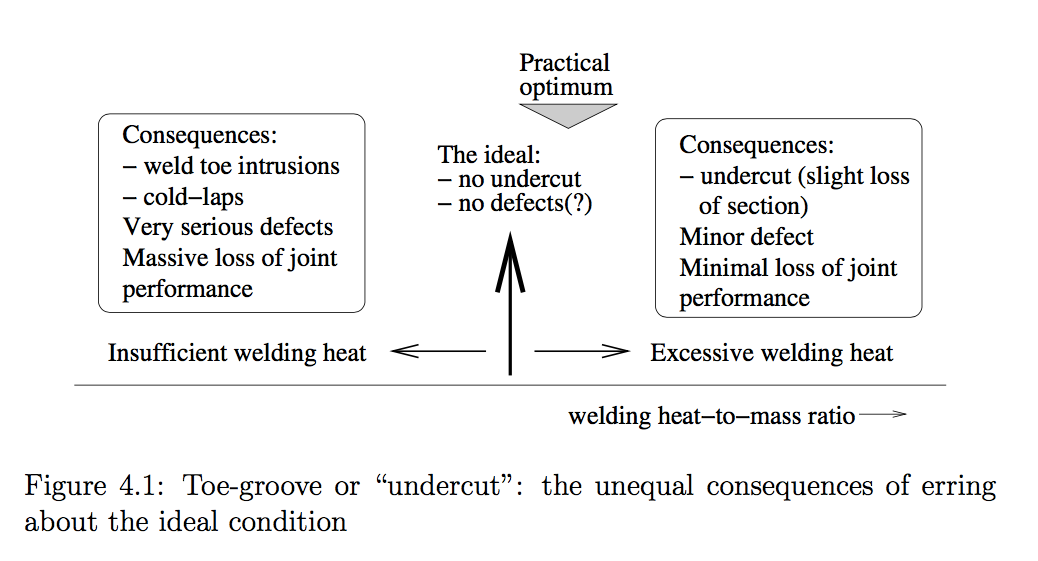
This is mainly about weld "toe intrusions". I provide metallography showing the "Signes, Baker, Harrison, and Burdekin (1967)" toe-intrusions, with the early-stage fatigue-cracking they have initiated - toe-intrusions with fatigue cracking
Exasperatingly, given this would have completely resolved the issue if confirmed, I did not have time to section the "my specification" sample with high fatigue performance to observe whether or not it had an absence of toe-intrusions.
As both a scientist and "coded" commercial welder, that welds can now be welded without toe-intrusions seems reasonable to me. In brief - with (linked cascade of points)
Contemporary computer-controlled eddy-current Non-Destructive Testing (NDT/NDE) methods now have enough acuity to detect toe-intrusions. The goal is "100%"/"full" post-weld inspection showing there is zero toe-intrusion in all the welds of the structure.
Rectification in the case of local short non-systematic toe-intrusions would dressing, probably with a "finger" stone in a die-grinder. Giving a local concavity probably less than 0.5mm depth when repeat NDT shows fully-sound metal.
I found the "my specification" weld condition when out of curiosity I
investigated if the FCAW could give a weld I would trust if I saw it
on a construction site doing the steel erecting.
Such a weld would be considered "in poor style" in the current world
of "WPS's" and "welding inspectors".
It seems to me that style orthodoxies and Standards have come together
to systematically put welds at a "pessimum" fatigue endurance.
("optimum" is "the best overall outcome", and as "pessimist" is
the opposite of "optimist", it would follow that "pessimum" would
signify "the worst overall outcome")
It is my perception that current style orthodoxies, which have some "two-way" / "in-and-out" relation to Standards, are unknowingly enforcing a systematically "pessimum" fatigue performance.
A weld made with the weld-pool fluidity which gave the "my specification" fatigue performance has
For general architectural steelwork, it is the "wetted edge" by which a welder identifies the sought welding condition, and what gives steel-erectors on-site the confidence that "they can trust their lives on these welds" if they see it inspecting the steels arriving at the site.
It is the collision between the perceptions of
Unambiguously, where excessive and a flaw / defect, it is ISO6520-1:2007 number 501 (5011 (continuous) and 5012 (intermittent)) - which is applied in ISO5817:2007 when quantifying what amount (magnitude and extent) of the feature is considered a defect.
In contrast; the "to WPS" FCAW weld would be considered in immaculate style:
I illustrate my perception of the situation as follows :
In summary; the challenge ahead is not solely technical, as there will be a need to influence some adjustment of Standards and design Codes.
The complexities of welding, which is dependent on many different physical laws of the Universe, across a wide spectrum of sciences, has made this section hard to write and only introduces to some of the key issues and the complexities.
Over the Christmas holiday 2020/2021 I managed to read some published engineering "papers" considering using high-strength steel for welded steel bridge construction.
I find that high level engineering analysis according to Codes for
bridges does not yet show knowledge that fillet welds can exhibit a
long fatigue crack incubation period.
(certainly also true for butt welds, but with less proportional
benefit given the lower SCF (stress concentration factor))
Completely rejecting a founding principle in the Codes. Therefore invalidating some higher-level analyses.
Papers looked at (I would not claim "read", as this would take specialist structural engineering knowledge) include
Oskar Skoglund, John Leander, Raid Karoumi
Optimal design of an arch bridge with high performance steel for bridges using genetic algorithm
Engineering Structures
15 October 2020
EU's
Optimal use of High Strength Steel grades within bridge (OPTIBRI) Final Report
of 2019
The useful aspect is that, knowing "the fatigue endurance problem" (fatigue resistance is given no dependence upon steel yield strength), the investigators progress their analyses according to every other part of the Code. Finding useful benefits if the new designs were permissible. Savings in cost, weight (therefore enabling more "payload" on the bridge, transport costs during construction, etc.), to the environment, and other evaluations.
To the best of my ability to outline what the structural engineers
considered : there may be structural design constraints impinging on
using higher strength steels. Such as buckling resistance
(Wikipedia : buckling)
.
Where, while higher strength would permit less material thickness and
therefore less weight to obtain the same load-bearing capability of a
structural member, that might reduce the thickness to less than what
is needed to make the structural member stable against local buckling
(that being a function of overall section dimensions, any steel's
almost invariant Elastic Modulus - and thickness).
With all these considerations, they did retain significant advantages.
Knowing that weld performance in cyclic loading can be much improved, the potential benefits "which would be available" are available.
These "papers" considered a common type of bridge for "medium" spans, a "hybrid bridge" (steel beams under a concrete deck, with structural coupling between the steel and concrete), with steel beams taking the tension and the concrete deck taking the compression of the beam-loading.
It might be that high-strength steels with high fatigue performance welds show greater advantage on large bridges, and infrastructure projects where long spans contribute to economy.
The first step must be to confirm or reject the finding that, by using good welding conditions, samples representing production welds can show a long crack incubation period in fatigue testing.
Were that confirmed:
test whether higher strength steel welds show a longer crack
incubation period at the same fatiguing stress cycle.
Explore higher-strength steels behaviour at this stage in order to
know what must be part of an engineering design information test
programme.
It is a guided guess that these tests would select a smaller
repeatedly-used size, like 6mm leg-length for single-run welds and
10mm or 12mm leg-length for a 3-run "multi-run" welds.
As these welds would be big enough to be representative but small
enough to give very economical small convenient tests - possibly where
many could be done "in parallel" to quickly build-up an "S-N curve" of
outcomes.
All being well, whether or not higher-strength steels give a higher
fatigue crack incubation severity performance, for whatever is found
there would be a wish to make good representations of welds used on
structures like bridges and find what their real performance is.
The performance of the steels might become as much part of the test as
the performance of the welds. For example - the effect of different
through-thickness ductility rating (the "z properties") for the plate
steel used could be examined as a variable.
This follows if crack initiation as a large part of fatigue endurance is confirmed.
With higher-strength steels favourably utilised as "closed" hollow sections, the assurance from continuous condition monitoring by pressure differential favours migrating to much higher operating stresses. With the guarantee that [cascading points]
With higher stresses, once a fatigue crack has formed, the remaining
fatigue endurance of crack grow to total failure of that structural
region would be short (days to weeks).
Contrasting to conservative designs where fatigue endurance is
entirely crack growth phase - but those cracks are slow-growing and
(expensive!) periodic inspection is enough.
Previously mentioned:
Report on
"Improving fatigue performance of steel T-joint welds - a pilot study"
,
a project as part of my Welding Engineer qualification, as a "PDF" of
3.2MB size.
Website with details of same project:
Fatigue performance of welded steel structures
Newly introduced:
My commercial industrial / construction work on a large project (about
US$2.7Billion)
Memoir - the 3rd Bosphorus Bridge project, Turkey, 2015
.
which has a section
"The story of fatigue-resistant weld design".
The construction of the bridge was stalled on only just starting the
steelwork phase, which resulted in my recruitment. This was a
rollicking story, getting people's heads out of their paperwork and
arriving at a strategy to get the bridge built.
Most of the other sections on Non-Destructive Testing and welding
technique served the fatigue-resistant weld design challenge.
On recently demonstrated profound ability:
The extent of the test programme leading to this document, done as a
sideline in a short period of time, illustrates the point.
See
Steel Structural Performance index-page
where some of the articles will be recognised already, while earlier
ones will illustrate the ability to open-up a path forward.
A lot of detail and explanation has been provided.
This should not distract from significance that a fillet weld has
showed a fatigue endurance unbroken in cyclic loading at 5.9 times the
predicted endurance to failure.
Which is getting close to the inherent fatigue endurance of "mill" steel plate
and sections tested it is intended to join.
Which is remarkable, in-itself, and in the ramifications for steel structure.
(R. Smith, 01Jan2021 to 03Jan2021, 09Jan2021 (credentials), 10Jan2021
(edits, some additions), 16Jan2021 (additions, ClassF ClassB),
07Feb2021 (bcfwtt rig pic, cond.monitor, edits, more evid. cred.),
22Feb2021 (fea bcfwtt), 12Mar2021 (100%NDT))