The test has been called the "beam-configuration fillet-weld tensile
test" - but is it truly tensile upon the test fillet weld ???
Anything else is subsidiary to that question. As, if the load on the
test fillet weld isn't "pure" tension, the test has much lesser value.
The physical test "in real life" - see:
Tensile-test rig for beam-configuration fillet-weld samples
plus with more pictures - first BCFWTT (sample identical),
Fillet welds tensile tested in beam test
Firstly - is the load on the test fillet weld pure tension brought by
the top surface of the sample beam?
That being so...
For the test fillet weld at break - are the measured force needed and
the
observed fracture mode
predicted by FEA?
Two simulations, sequentially
You may want to jump ahead to the detailed BCFWTT weld-region simulation , accepting that consideration of the overall beam configuration test indicates it works as it should.
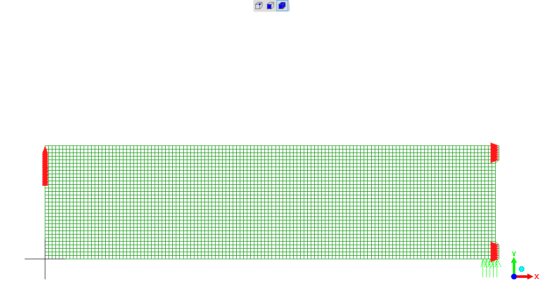
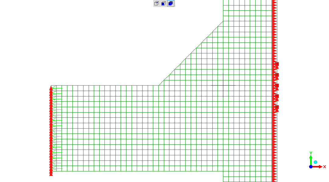
To the right-hand-side edge of the model as constructed is a plane-of-symmetry. So the representation is the left-hand-side half of the complete beam sample.
This model is qualitative only !
The "beam" is a solid cuboid.
The size is not literal.
The force applied is arbitrary.
etc.
Its sole purpose is to assist in a qualitative visualisation of the origin and destination of forces, and the flow of stresses.
What one would desire is a state of pure tension applied to the weld (located at top right-hand-side of represented beam).
Beam deflection is shown magnified 100000X times.
I am challenging viewers to consider whether I am right in evaluating these forces and stresses, and make informed comment.
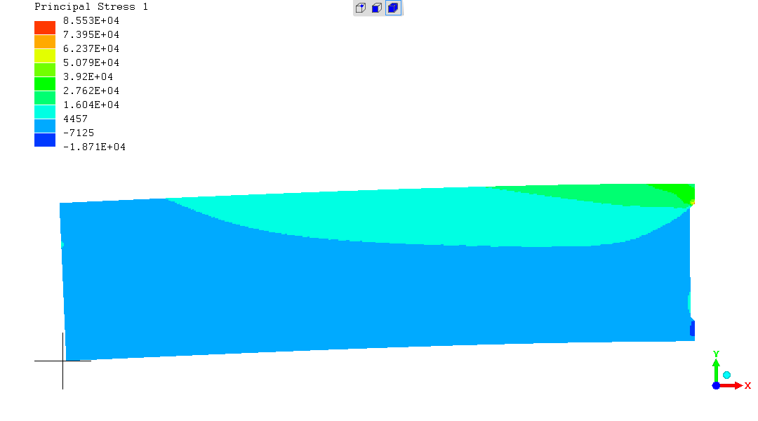
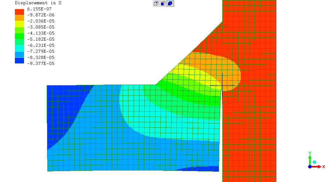
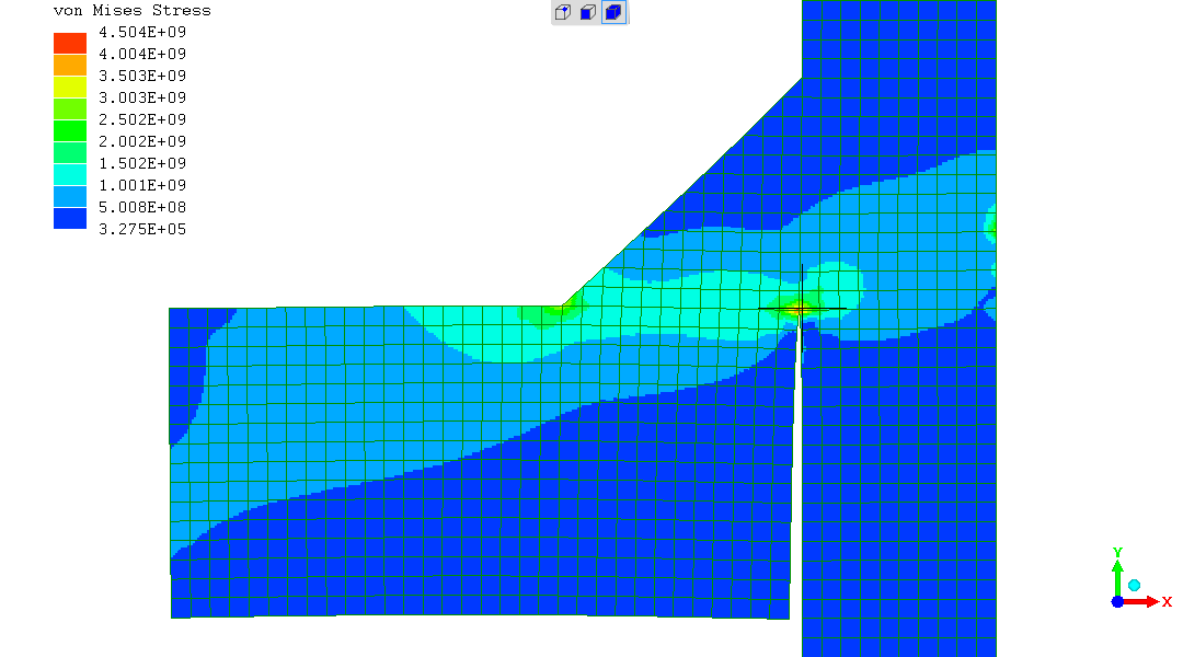
Quick digression - in this unusual case "von Mises" [Wikipedia] isn't helpful - almost misleading, as
"Principal Stress 1" seems most useful.
It seems to me that it is possible to separately visualise - intuitively; from the analytical derivation see section "Stresses in weld analysed" ; and only partly from the FEA model :
This model is the left-hand-side half, given a plane-of-symmetry to the right-hand-side of the model.
Conditions - dimensions; materials; loads; constraints - are believed to be completely representative of the BCFWTT at the point of failure by abrupt fracture in test.
In particular - 14Tonnes-force (137340N) across the weld of 6mm leg-length and 40mm weld length.
SI units used, so
Shown with deflection magnified 4X ("4 times").
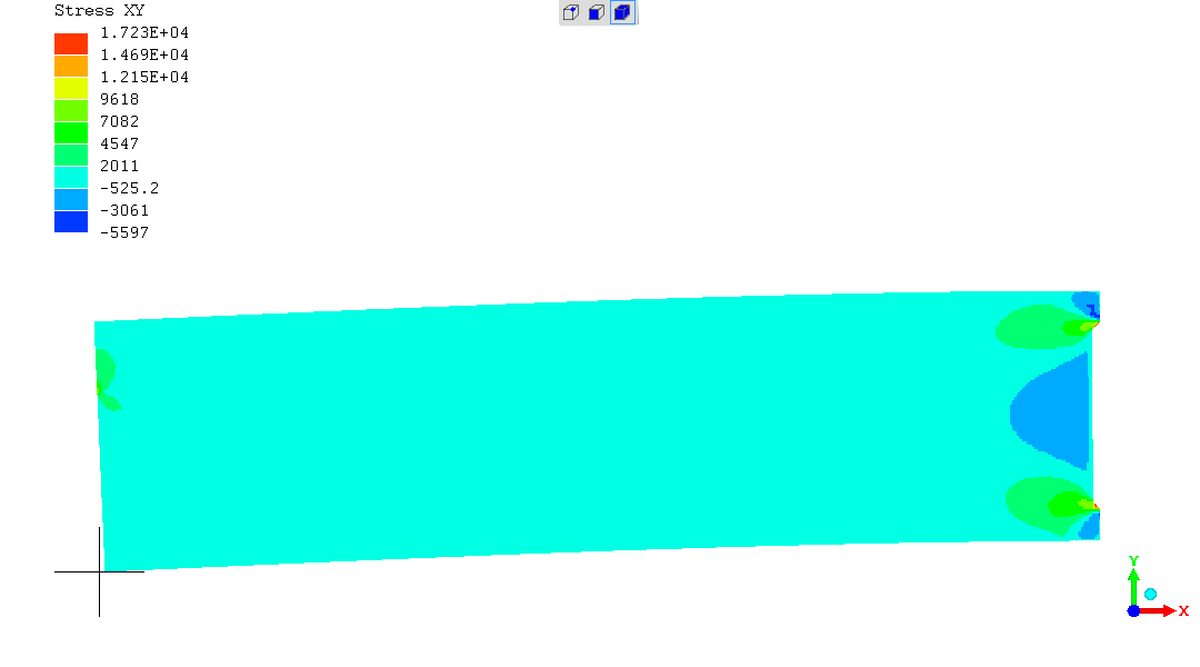
FEA "Open cracks mode" reveals the horizontal "plate", representing
the top surface of the Rectangular Hollow Section, coming in from the
left-hand-side and terminating against the vertical "middle plate".
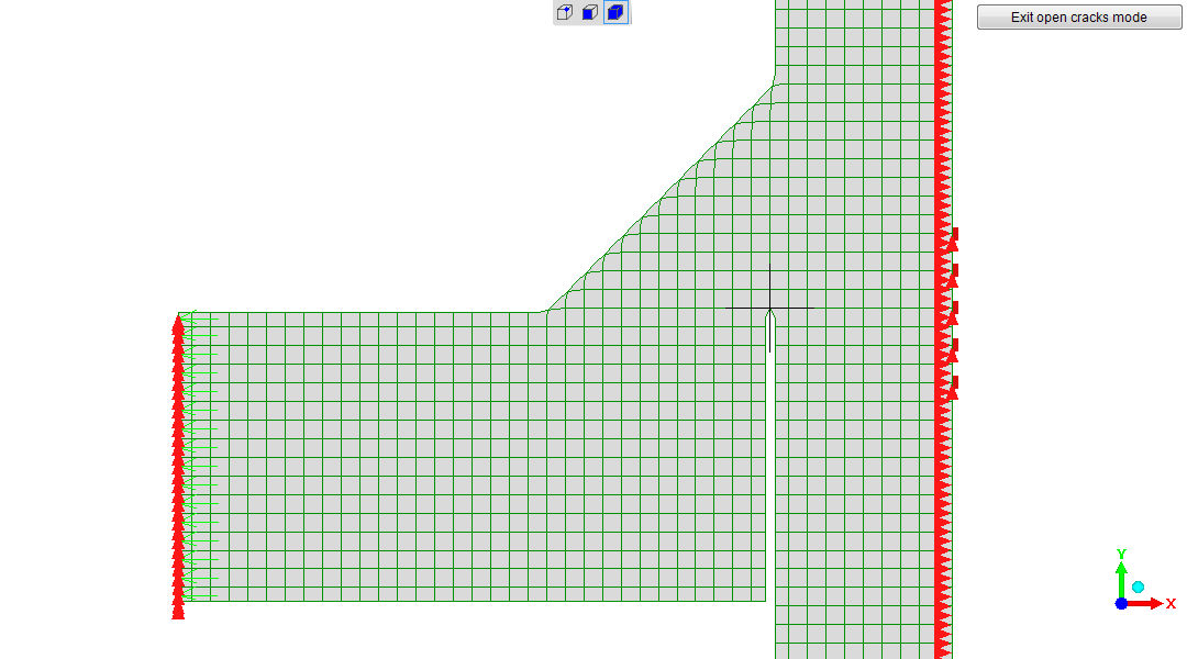

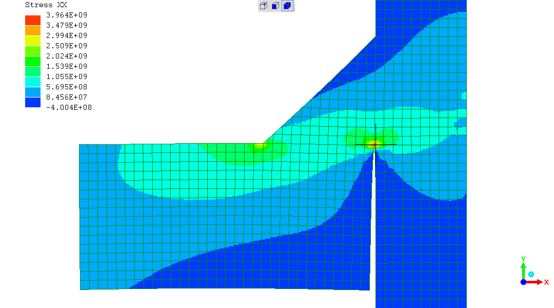
The highest stresses are predicted to be along exactly the region
where the real test weld is
seen to fracture
.
So the FEA model and the real test do correlate.
With
That is unequivocal.
I am soliciting mentoring on interpretation about forces, stresses, their interpretation and their effects on the following...
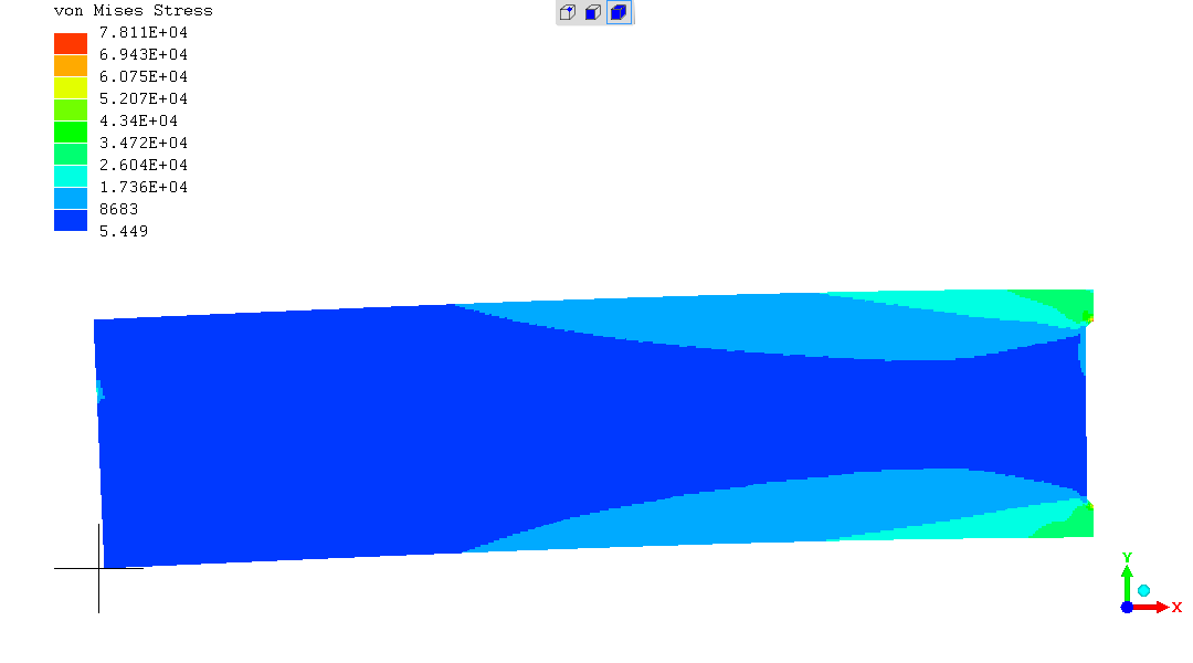
"von Mises" is showing a band of regional stress well above the known breaking stress seen of around 560MPa, along the longitudinal fillet "leg" (edge of the "triangle" of weld metal meeting the parent plate) - which "isn't good news" for survival of that region.
Other measures of stress are concurring.
The local point of extremely high stress at the "root" / "fillet
corner" should not be taken too literally, as this is infinitely sharp
in the model - but has some microscopic but finite radius in real
life.
Also... As seen from the magnified deflection representation of this
single-sided fillet weld - there is some rotation of the parent plate
under load - which will intensify the stress at the fillet corner
further. Where many fillet welds are double-sided, which makes
rotation under stress tend to zero, and in reality
random-and-negligible.
That said - the real fracture surface has its inner side from around the fillet corner - while the outer side "hits" the weld surface just above the weld toe. So the "von Mises" stress concentration at the weld toe cannot be fully compelling the fracture to go there.
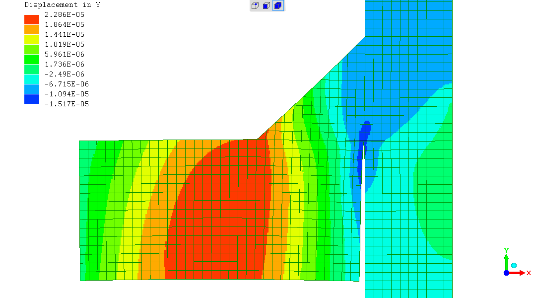
Attention went to whether the horizontal "8mm thickness" plate is
rotating under load and intensifying the stresses in the weld-root /
fillet-corner ?
Considering the magnified deflection, and the "Displacement in Y"
output.
That being due to a Moment ("twist") caused the beam's cross-section and the fillet weld not being in-line for the forces flow through them. That Moment causing the horizontal plate to rotate / "twist".
I find that's not the case according to the FEA. That when I model with a 15mm thickness plate, while the rotation under load is much reduced, it makes a very minor difference to the stress in the weld-root / fillet-corner - and elsewhere.
I've provided a comparison page between the "actual" 8mm thickness and a hypothetical 15mm insert thickness.
That said - in the "real world" of the physical test, as any experimenter would do,
There is inexactness about finer details of the interpretation of the
FEA in relation to the real outcome. However, the dominating overview
is of theory as implemented in the FEA model predicting the nature of
the fracture on overload of the BCFWTT.
Plus concurring that the force to cause fracture in the real weld
looks like a breaking condition in the FEA model.
To put it in perspective - the established analytical / mathematical model for fillet weld strength has fracture through the fillet throat (its shortest thickness "on the 45degree" from the fillet corner to the weld face). Which is not correct. As discussed elsewhere .
Good outcome here.
(R. Smith, 05Feb2021, 06Feb2021 (dy, 15t), 07Feb2021 (anames, edits), 08Feb2021 (tensile q))