This test answered a need to focus the most severe conditions in the sample upon the test weld being investigated. ie the test weld is the clear focus of the test procedure.
In a recent very interesting and rewarding learning exercise, the "U-frame RHS test" , a complimentary next test with this property would be needed to severely test welds and complete the range of information gained.
Considering the need, this test was visualised, which when implemented fulfilled that objective.
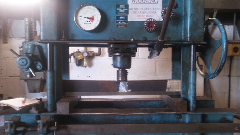
First-off - conveying an impression of how the tests were performed...
Seen in overall picture of test setup:
Jump-ahead to immediately see effect of tests on the sample.
A straight beam supported at the ends and loaded in the middle has a highest stress at the mid-span.
What is meant here is a "simply supported beam" - which has an
extensive agreed definition - and a point central loading.
Broadly, it you visualise a typical floor-joist in a house, the
conditions meant are there.
Therefore
The "half beams" are compatible with the weld, but are less stressed, so the properties of the weld will dominate the outcome.
What is being done here is the exact opposite of what one would normally do being pragmatic when making a structure, which is to avoid welding near the middle of the beam. If it is necessary to butt beams together to make a longer length, put the longest stock length in the middle, and weld extensions towards the ends...
One attraction of this "simple" (?!) scheme with the sample as a straight beam
is that the expected load-bearing ability and expected elastic
deflection under load can be calculated with the Euler-Bernoulli beam
equations.
That is - this situation has an "on-paper" arithmetic solution
(as contrasted with computer-numerical solutions
("number-crunching")).
Another fundamental attraction is that "axial" tensile tests require enormous applied forces and huge testing-machines - whereas beams can reach high stresses at moderate applied loads within reach of common general-purpose press.
The end supports for the test beam with test weld are set at 600mm gap between these supports.
*** mathematics not explained - study Second Moment of Area and Euler-Bernoulli beam equations if desired ***
To be calculated:
The Second Moment of Area, "I", of a square-cornered rectangle of the
overall dimensions of the RHS = 2.443e-6 m^4
(using "bh^3/12" and subtracting 2ma-void from 2ma-outer)
Section Modulus, "Z" = 2I/h = 4.886e-5 m^3
Combining geometric properties with material properties to get service
capability of this beam / RHS - the maximum Moment;
M_max=sigma_max.Z
M_max=355e6*4.886e-5
M_max=17347 Nm
F_max=4.M_max/L
F_max=4*17347/0.6
F_max=115644 N
Converted - that is 11.8 Tonnes-force.
Deflection - for a simply-supported-beam
y=FL^3/48EI
Taking the elastic modulus as being 210GPa
y=F*0.6^3/(48*2.1e11*2.443e-6)
y=8.771e-9.F
From the calculations for force at onset of yielding, we have
F_max=115644N
so at onset of yielding
y=1.014286e-03 m
or almost exactly 1mm.
Which is "small", in that "error" (in the strict scientific /
experimental meaning) will easily overwhelm the attempted measurement.
An economical slightly naughty way of illustrating the under-load state of an Euler-Bernoulli beam is to grab the colourised renderings output of a Finite Element Analysis program modelling the beam.
This FEA model is very economical so is notably finely discretised, so the "exact" agreement between "exact" analytical equations and "approximate" FEA is a special case, be advised.
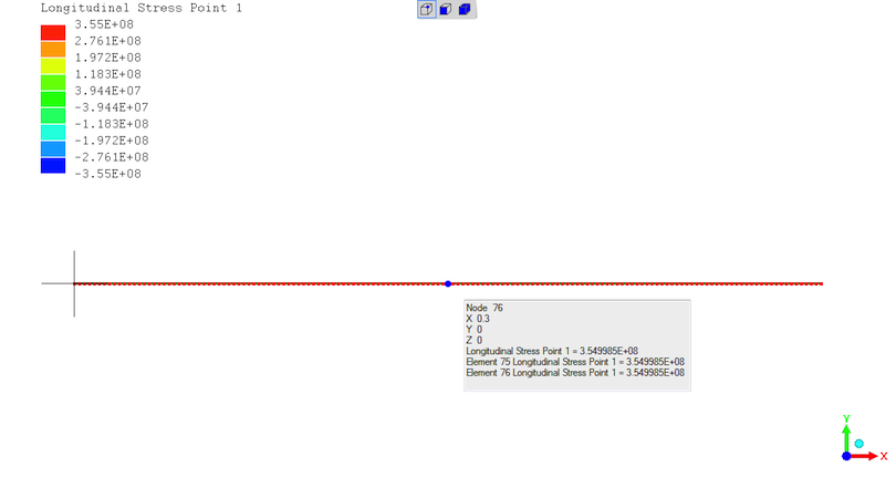
Exact agreement on stress - "3.55E+08" = 355MPa at the midspan for a 115644N load.
(the 2 sets of 5 black lines are " rendering artifacts" with no real existence)
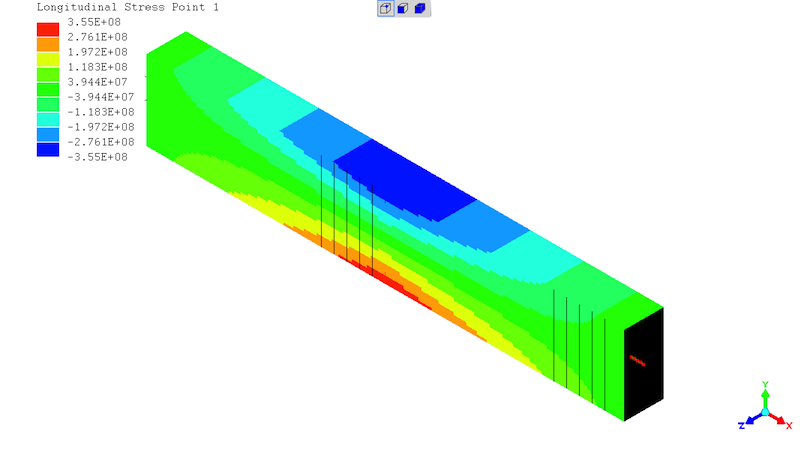
State of stresses in the beam - highest stresses at the mid-span with "negative" compression at the top and "positive" tension at the bottom.
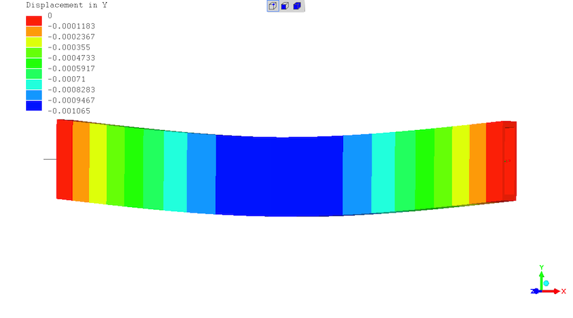
Beam deflection off straight. In metres - so max. deflection is 1.065mm. Colourised and deflected shape represented at 20X magnification.
The test beam with test weld is shown when the press has been
pumped-up to 17.6Tonnes-force, which is 1.5* the predicted force for
the onset of yielding.
There being nothing obvious to picture at 11.8Tonnes-force of
predicted onset of yielding.
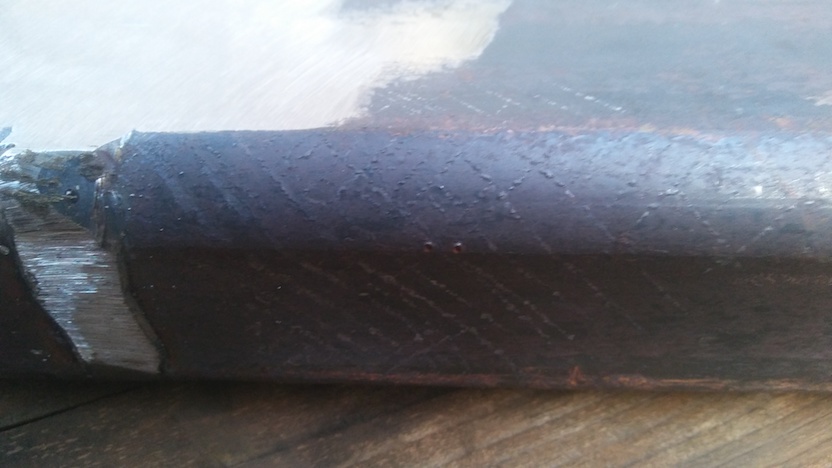
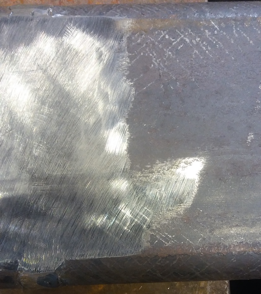
The major "witness" to yielding are the Lu..ders (L u-umlaut d e r s) bands across the surface of the sample.
The Luders Bands have spalled-off the mill oxide coating on the RHS's, at angles to the beam axis tending to 45deg - which reasonable given shear is maximum on the 45deg inclinations.
In the last two photographs, bands are seen on the 45degree inclinations across the "silver" metal, supporting that these are Luders Bands.
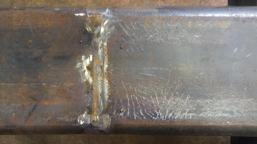
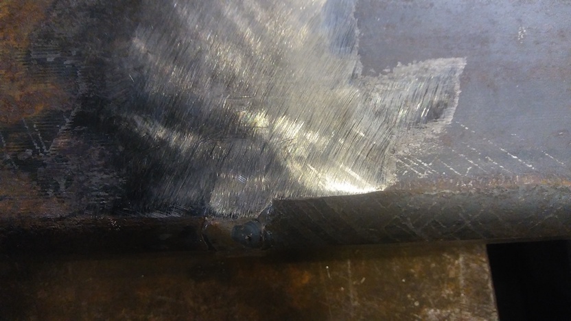
The weld has no Luders Bands as can be observed - which is not
surprising given the fine uniform structure of good welds. That said -
the weld and the steel of the RHS are coupled, so the Luders Bands
provide direct proof that the weld is being severely tested.
As intended...
As best as could be observed, and sensed through the lever of the
hydraulic pump, the sample did reach yield at the predicted forces of
11.8Tonnes-force.
Luders Bands began appearing just over this force.
On releasing the press force, the beam maintained straightness up to 11.6Tonnes-force, but was visibly bent as seen when placed on a flat surface after more than 11.6Tonnes-force had been applied.
The deflection-under-load at 11.8Tonnes-force was measured as 1.5mm - which is indistinguishable from 1.0mm predicted given the likely experimental error.
At 17.6Tonnes-force, the measured deflection (certainly a mix of both elastic and plastic deformation) was 4.6mm. There is no expected value by Euler-Bernoulli theory after the onset of yielding is passed.
Wishing to recover the test beam for other uses, the beam was inverted
and the press was pumped-up. Leading to the observation that the
force which caused the bending (17.6Tonnes-force) was the force which
returned the sample beam to straightness on releasing that load.
There was a large amount of movement at the same force, just
approaching 11.6Tonnes-force, as judged by the number of strokes of
the hydraulic pump with the force to pump remaining essentially
constant.
There are complex metallurgic effects in elapsing time about
yield-drop and recovery, which are probable here given there are
Luders Bands, so it is not possible to say whether the effect is only
observed if the force is reversed just after applying the force which
caused the bending.
This test worked very well indeed, for intended purpose.
Given the test was most testing of the weld's properties.
The materials measurement objectives were met, and the readily
available equipment easily performed the tests.
The is abundant supporting evidence that the test is reliable and does
what theory expects.
The Euler-Bernoulli equations do apply, making the test conditions
easy to predict and the findings open to quantitative analysis.
(R. Smith, 24Nov2020, 29Nov2020 (added FEA beam images))