FEA = Finite Element Analysis modelling
This is the previous steel BCFWTT with the material changed to Aluminium (Aluminum) properties
This is a linear-elastic FEA model.
Sunday 04 September 2022 - repeating previous caveat - there has never been an independent review of this FEA model.
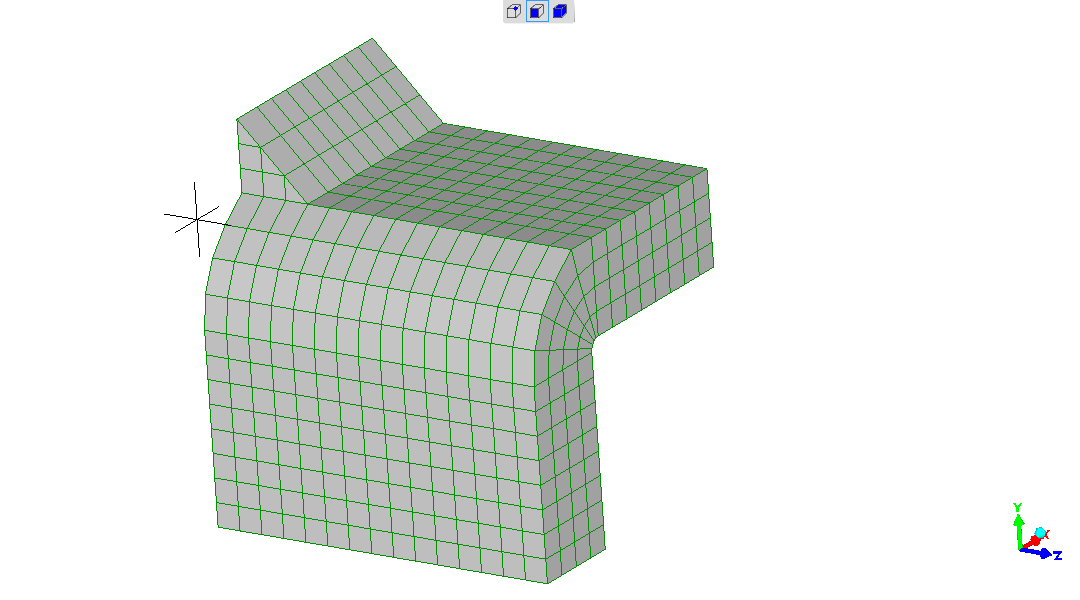
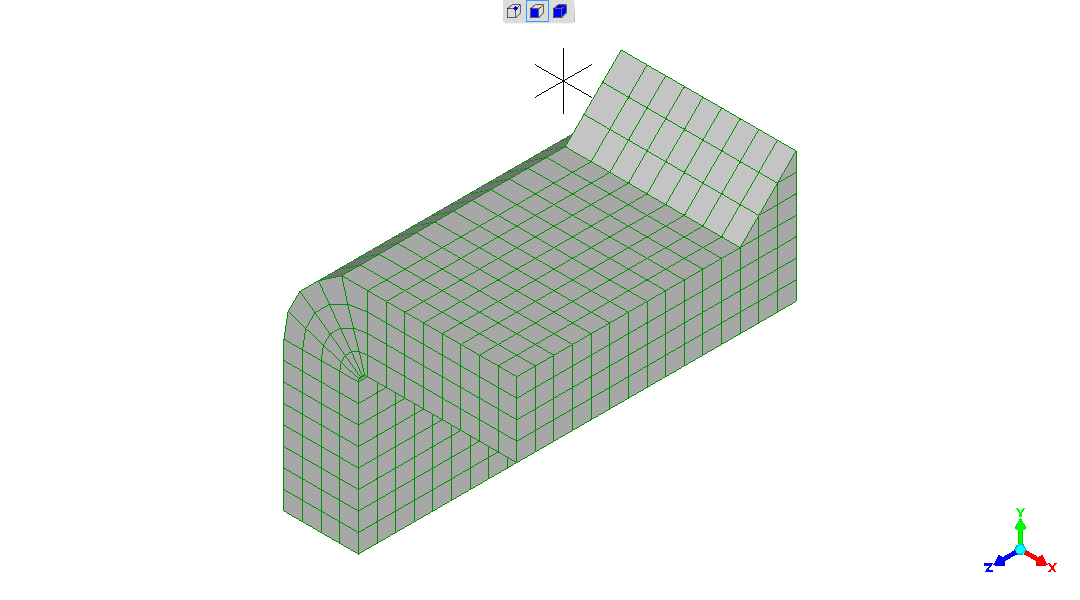
BCFWTT = Beam-Configuration Fillet-Weld Tensile Test
As seen physically
in the test rig
.
In most ways this is an exercise in pointlessness.
The Finite Element Analysis solution applied is linear-elastic.
Getting away from specialist terminology - that means things (stresses and strains in this case) vary in a simple directly proportional way to inputs applied.
Thus - double the load(s) applied to a structure - you will double the stresses and strains.
Thus; whatever the complexity of the linear-elastic FEA output - and a general method to predict the spectrum of stresses flowing across a structure of any shape was a "holy grail" until a few decades ago - if you increase the forces applied by 1.23X, at any given location in the structure the local stress is 1.23X and the local strain is 1.23X.
So in a linear-elastic FEA solution, if you make the Elastic modulus ("Young's modulus") 1/3rd of the previous value (E(steel)=210GPA; E(aluminium)=70GPa), all the deflections increase by 3X.
Which is exactly what is seen.
That can be looked for and seen comparing the BCFWTT solutions for
steel
and aluminium (this solution; this page).
The effect of changing the
Poisson's Ratio
[Wikipedia]
(Poisson's Ratio (steel) is taken as 0.3; Poisson's Ratio (aluminium)
is taken as 0.33) is too small to see in any obvious way in the
results, comparing the simulations for steel and aluminium versions of
the Beam-Configuration Fillet-Weld Tensile Test.
Being a linear-elastic solution - if the Poisson's Ratio were
unchanged, the stresses at locations for objects of the same geometry
and loading would be identically the same.
The way I visualise "linear-elastic" for a linear-elastic finite element solution is - the modelled structure (the structure represented in a parallel world of numbers and equations) is completely unchanged (shape, size) by the applied stress, and the answer is how much the structure would have developed stresses and strains. That hypothetical structure stays completely unchanged (shape, size) by any applied condition. Which is why the predicted answer is always simply proportional to the size of the inputs (load in this case).
Pertinent comment would be that there is no point looking for non-linear effects with a linear model.
All explanation of the model - see the previous
steel BCFWTT model
,
which is otherwise identical apart from material properties.
ie geometry, constraints, loadings, etc are identical.
Without explanation : redisplayed here:
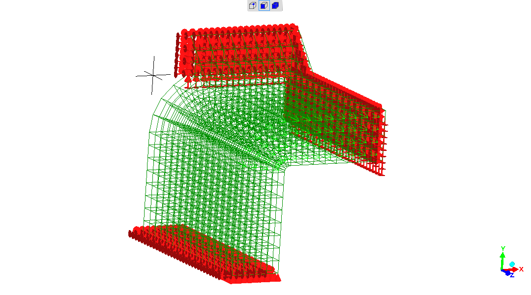
What has also not been changed is the load applied.
This would give a shear stress of 560MPa on the longitudinal leg of the fillet weld, given
The loadings in the steel BCFWTT FEA model are what is known to
cause the physical samples to break.
The breaking load and therefore stresses for the steel samples are not
what theory predicts.
This makes it difficult to know what load should be correctly applied
to the Aluminium BCFWTT model, so that the stresses at the instant of
breakage can be examined.
Given no physical test has yet been done.
The simplest choice is the one applied : leave the loading the same as
for the steel BCFWTT model.
Being a linear-elastic model, strength is not a property represented
(the model material implicitly has infinite strength).
Given the major imponderables, the advantage gained is that the most
comparable steel and aluminium BCFWTT test simulations are obtained.
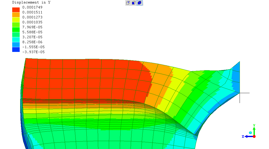
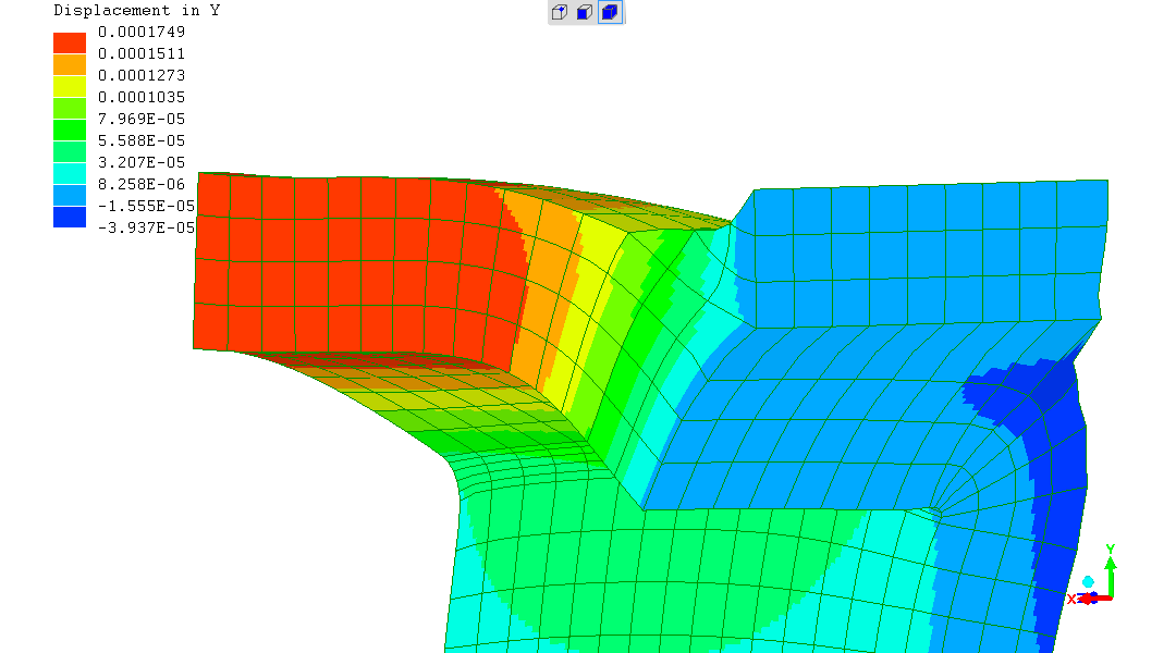
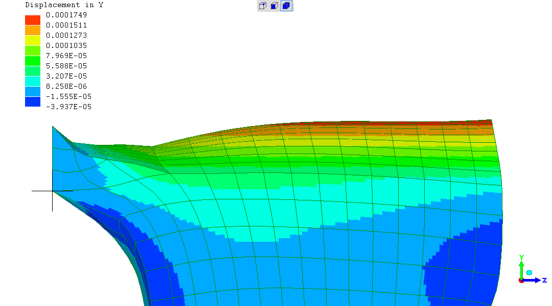
All outputs have displacement magnified 40X.
This is the same as for the
steel BCFWTT model
,
producing a more exaggerated portrayal of deformations than usual
(the FEA software offers a magnification of about 13X, given the
larger deformations it finds)
but instructing 40X deformation magnification gives easy comparability
to the aluminium and steel BCFWTT models.
Being mindful that the very exaggerated deformations possible amount
to distortion of the view.
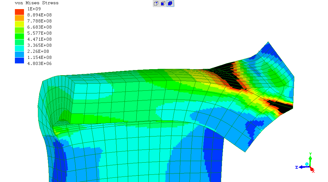
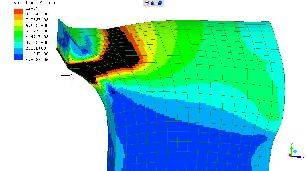
The model is built in SI units, so the output values are SI units.
The black regions around plane where weld metal joins the top surface of the RHS is where the model stresses exceed 1GPa.
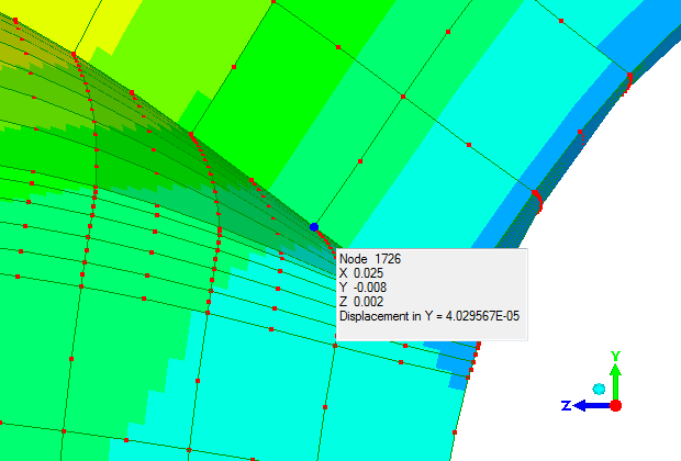
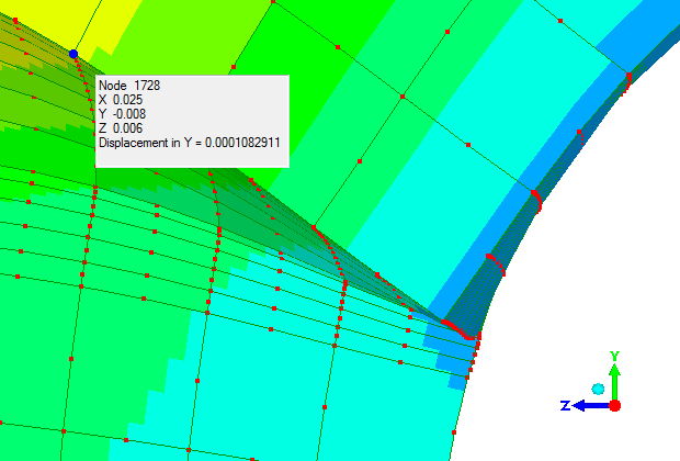
The "Angular displacement" ("rotation") predicted is calculated as seen:
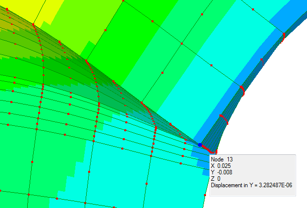
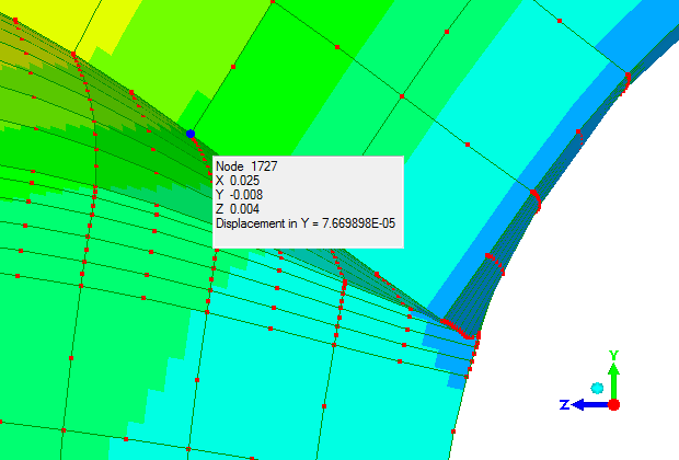
Between Node13 and Node1727, that is a rotation of 1.05degrees, or "1-in-54".
Between Node13 and Node1728, that is a rotation of 1.00degrees, or "1-in-57".
The deformations of the Aluminium FEA model are significantly greater
than for the steel FEA model.
Which is expected given the aluminium's Elastic (Young's) modulus is
1/3rd that of steel.
Given the FEA simulation is linear-elastic, any cascading effect ("non-linear effects") of deformations on stresses produced is not taken into account, so no comment is better.
(R. Smith, 04Sep2022, 05Sep2022 (l-e realism, edit final comment))