*** Tuesday 16 February 2021 - presented "advisedly" - just FEA modelled and not carefully considered yet ***
BCFWTT = Beam-Configuration Fillet-Weld Tensile Test
As seen physically
in the test rig
.
It is common for one FEA simulation to be unable to present the means
to inspect every issue of interest.
General comment : commonly, the build-time to the human to create such
a model is prohibitive, and the computational resources are infeasibly
huge.
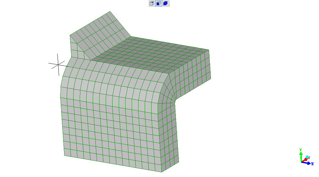
This model is expected to be
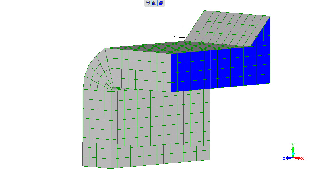
Elements faces at surface shown.
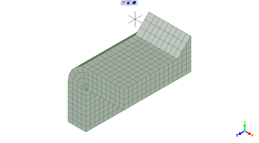
The Elements are mid-side-node Elements - eg a cubic element
has not 8 nodes of a corner-node Element but 20 nodes.
So, given the limited discretisation achievable, making it infeasible
to "chase" proof of "convergence", the accuracy should be at the
better end.
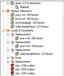
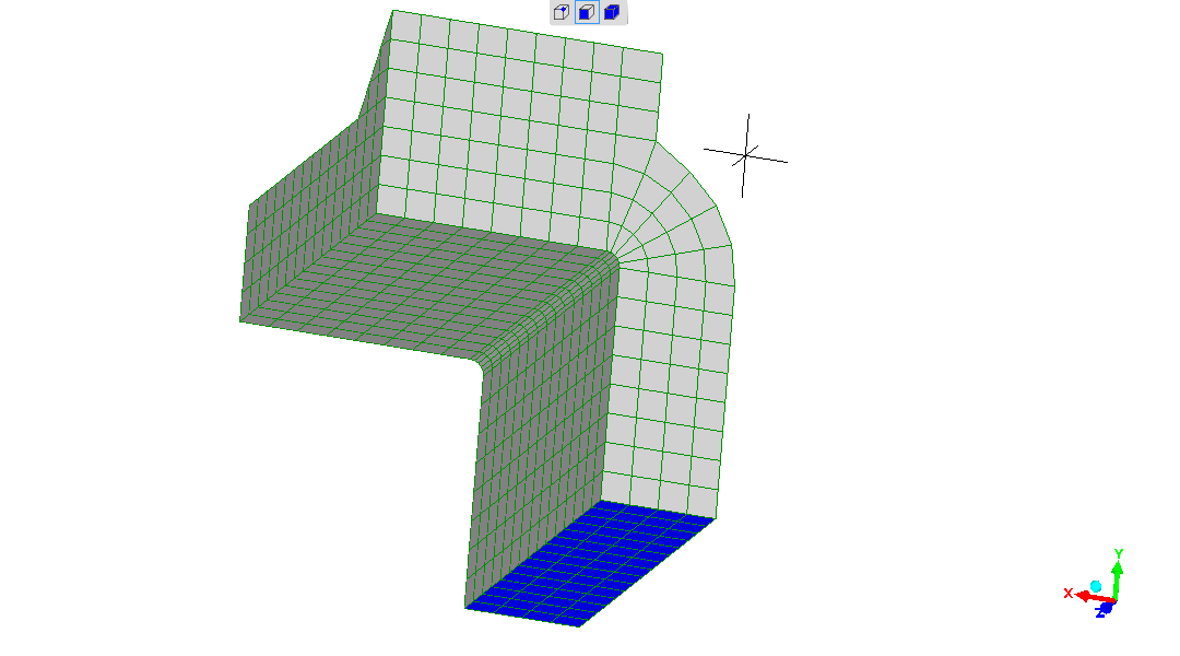
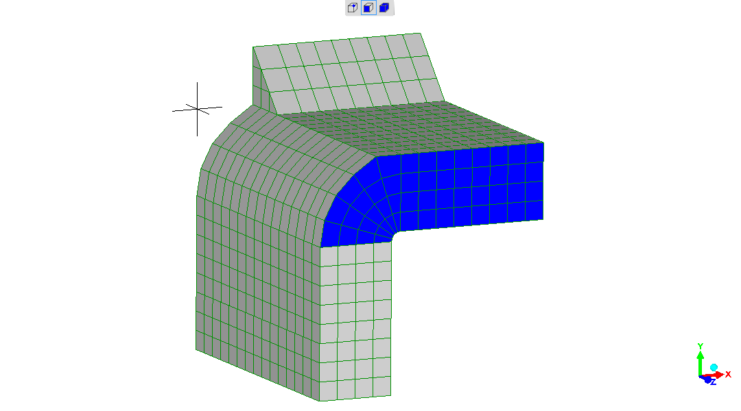
Constraints panel as-seen :
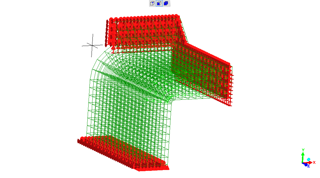
If this image is confusing to visualise, the same viewing direction is seen for "The force-application end face" but as surfaces-presented so should prove useful in that case (last in this subsection).
The constraints - seen through nodes and element-edges presentation.
"No displacements" and "no rotations".
Overview, as this is, for sure, a cluttered presentation.
This has a very real physical counterpart.
This does not have a real physical counterpart, but is necessary to to
make the model manageable in computing resources.
The "error" introduced is that the Euler-Bernoulli beam bending of the
sample beam is not present. That "error" is minimal and is surely a
lot smaller than other modelling approximations.
The Euler-Bernoulli beam top-surface stress is represented by the
end-force (see shortly).
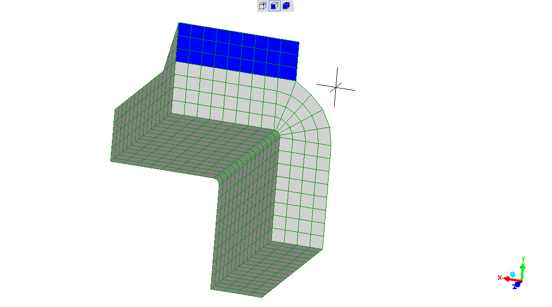
The green arrows denoting the force applied might be recognisable referring back to the "All constraints" presentation.
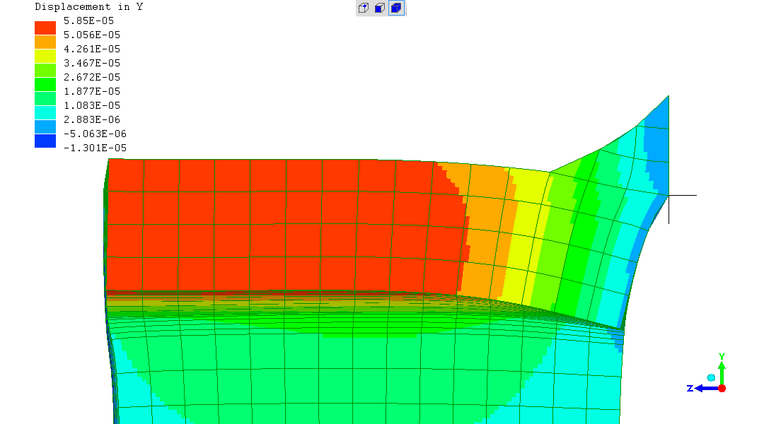
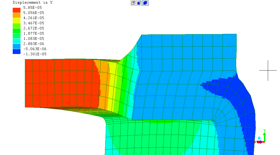
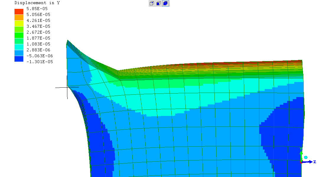
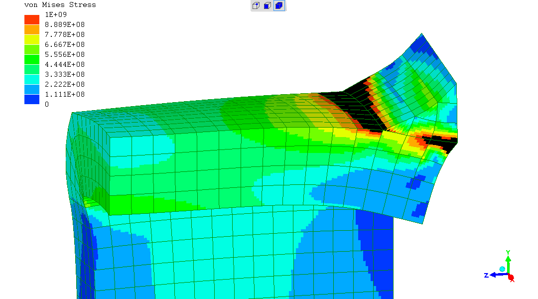
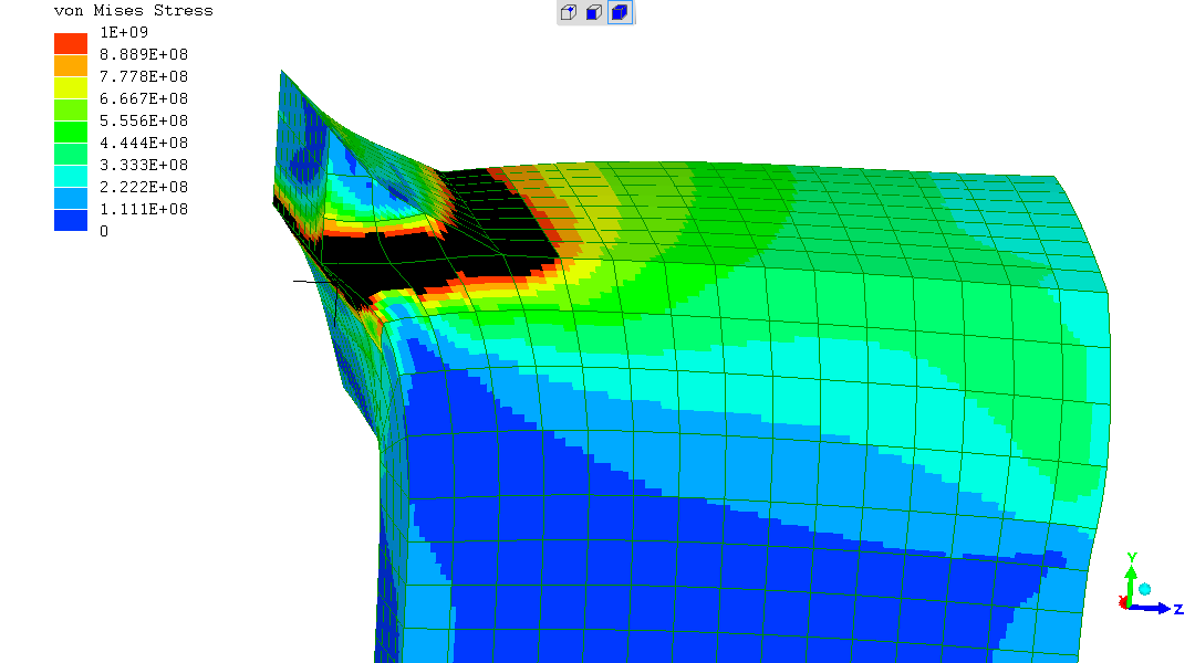
All outputs have displacement magnified 40X.
The model is built in SI units, so the output values are SI units.
Black regions around plane where weld metal joins the top surface of the RHS is where stresses exceed 1GPa.
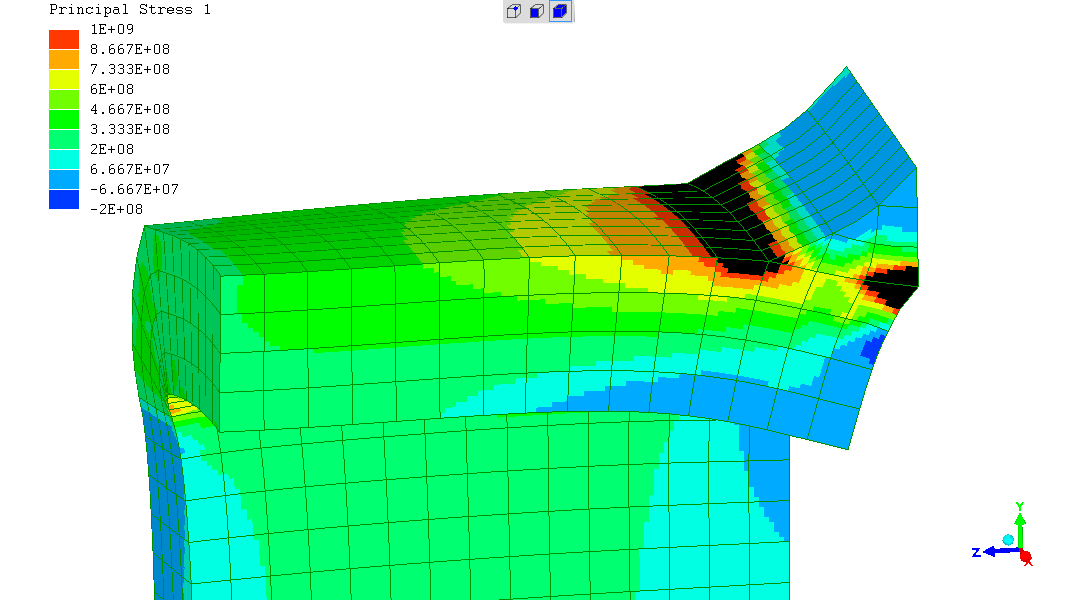
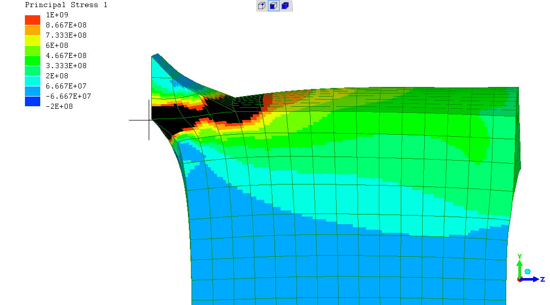
As with "PS1" - Black regions around plane where weld metal joins the top surface of the RHS is where stresses exceed 1GPa.
"Angular displacement" is not offered as an output on this FEA software. But can be deduced where it is of interest.
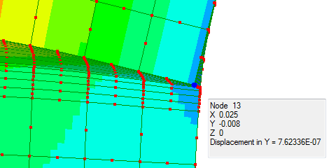
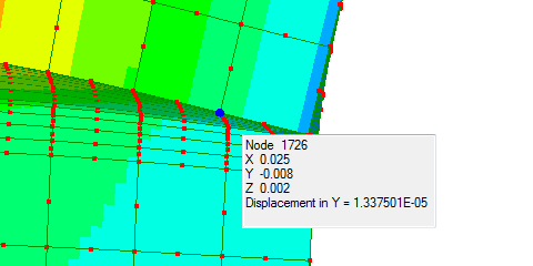
The trigonometric angle and gradient is the rotation of the beam surface under load / stress.
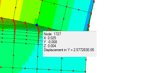
Between Node13 and Node1727, that is a rotation of 0.36degrees, or "1-in-160".
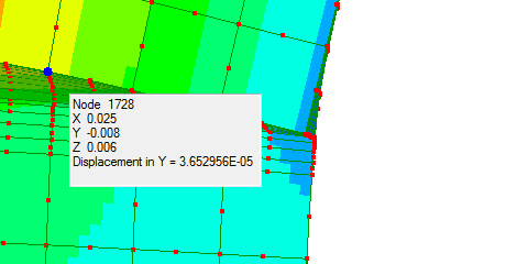
Between Node13 and Node1728, that is a rotation of 0.34degrees, or "1-in-168".
These are apparently rather small.
The 2-D simulations, which are believed to be very accurate for weld
stress, suggest the effect of the rotation on stress intensification
and highest stresses resulting is small. The evidence is where a
thicker plate is substituted, which much reduces the rotation but has
little effect on the stress profile - tiny reduction in the highest
stress.
(R. Smith, 16Feb2021, 16Feb2021 (more detail))