Structure of this page on the rod-mill (tumbling-mill) project:
These are the provisional thoughts at the outset:
batching - the "mill" will be loaded and run for a duration - no input or output (unlike a production mill with continuous inflow and outflow}
dry-grinding - so can sieve the output to obtain the size-fractions ?
on rollers - the "mill" will be a barrel on rotating rollers - rather than rotating on its own bearings - suitable for small "mills" and enables at junctures rapidly lift off barrel and upend, release "hatch", lift-out rods, and {inspect / scoop / pour out} ore in its current state to evaluate progress
different cylinders easily swapped - can try rod-mill(s), ball-mill(s), etc
Even as a batching mill, could wet-grind if trials have yielded a lot so far and comparison of dry vs wet grinding for the same mill is desired.
It is commonly the case that "simple" plans lead into an extensive and informative program, pursuing "interesting" earlier-stage observations.
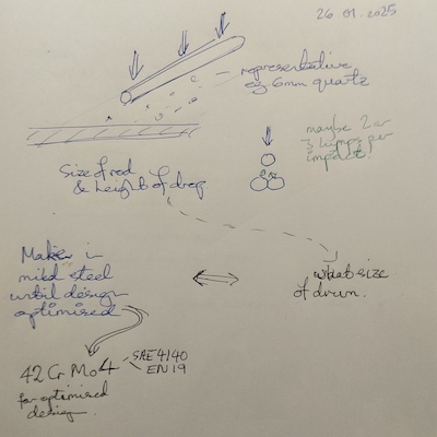
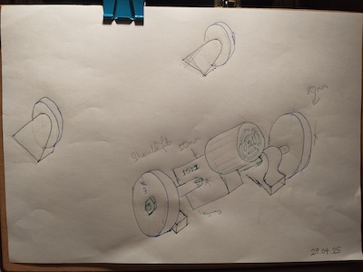
Intended empirical test shown following - sketch from late January 2025.
I conjecture that the bigger the shell and the bigger the rods, the larger the feed size can be.
Or put it another way - can a small shell size be compensated for by a larger rod size - which presumably would be at a "cost" of (much?) smaller "throughput" - mass of ore processed per unit time. ??
Anyway, the idea here is to take samples of a representative rock/mineral and find what height of drop for a given bar diameter and length rapidly breaks-up ("comminutes") the maximum feed-size mineral.
Taking it that capably breaking-up the largest feed size mineral is
the constraint, with smaller sizes readily breaking up as-and-when
their turn comes to be comminuted further.
These thoughts dive into the whole issue of a rod-mill with rods
having length preferentially grinding the largest "particles"
currently present. Where ball mills don't have that "coupled fate"
and anything between the tumbling balls gets more comminuted.
This whole exercise being about "seeing" the ostensible much tighter
size-range of comminuted material produced by a rod-mill compared to a
ball mill.
Noting
It might be that the "Version 1/4", "Version 1/2", etc. first
improvisations are too small to comminute the primary-crushed feed
size.
To which the easiest answer for pilot trials is do any secondary
crushing as converts the ore to a maximum feed size the
"improvisation" can handle.
Don't try to get all the answers / solutions "in one" is generally
good counsel.
Six weeks later I found confirmation of a conjecture I made at that time in January - thanks 911metallurgist - as follows:
... For the best results it has been found that the smallest diameter
ball or rod which will break down the particular material to be ground
is desirable since greatest surface area is obtained.
which continues
From the standpoint of economy, the larger the media the higher will
be the liner consumption and media consumption. ...
Tubes potentially useful as shell(s) for rod-mill / ball-mill trials have been collected.
As were some bars which could go in a "mill".
Obtained four bars of about 40mm diameter.
As seen here - "shell" and bars:
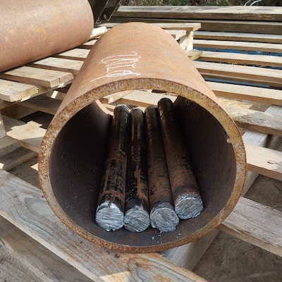
This tube is 220mm internal diameter
... and more that 1~1/2X as long.
There is also a slightly bigger dia. tube - but with less wall thickness.
I have some smaller bars already to make a mixed charge of rods.
Tubes and rods are "mild steel".
Which means they wouldn't last long. They will surely have rapid wear caused by the rock/ore were it successfully crushed/ground/comminuted.
On the other hand - iron as a contaminant from wear is not a "penalty element" for
Material - "mild steel" is readily obtained. Hopefully all coming
adventitiously. Hopefully as scrap and offcuts.
It is also, relatively to any alloy steel with specific properties,
very easy to work with - cut; weld; etc
Hard alloy steels are necessary for production equipment. True.
However, this is a whimsical "learning-curve" / "proof-of-concept"
activity.
In general - don't expend in durable materials until the form and
design is finalised upon accruing abundant relevant supporting
experience.
An alloy steel I am familiar with, 42CrMo4, is recommended for rods.
Which is a C-Cr-Mo alloy steel.
It gives good hardness for its cost. A question my mind did identify
and leave open, not explored, serendipetously got an answer anyway,
given the extent of local knowledge and conversations had. In larger
sizes 42CrMo4 would be "struggling" to attain the hardness in
heat-treatment it would otherwise promise. Answer - yes, and you do
push it to gain the high hardness. Which does leave some brittleness.
Which is an advantage because as the rod wears smaller while
retaining its length it can on getting twisted break ("snap"). Not
bend... You don't want bent rods - they tangle the mill, giving a
dangerous problem to deal with (in larger mills anyway). Broken /
snapped small rods reduce the throughput of the mill a bit. All dealt
with at next maintenance.
The shell "should be" liner'ed with a hard abrasion-resisting alloy too.
So this trial mill is being made out of mild steel for good reason, from a reasonably informed perspective...
Met an expert and with respectful brevity obtained his opinion.
With no comment, showed photo above. Expert - "You are making a
rod-mill."
Stated the as-seen tube inner diameter is 220mm and the four rods are 40mm diameter. Me - "How do I develop this?".
He reckons the bars are the right diameter and number for the largest. Need 30mm, 20mm and 10mm bars for the initial charge of rods.
The expert suggests try attach "paddles" to the bore of the shell to help carry the rods and ore around with the rotation of the mill.
He reckons the largest feed size such a mill could competently handle
is much larger than I guessed it to be. Around maybe 3mm to 5mm is
way smaller than the expert suggested might be so.
Okay; making mental note of possible maximum feed size while managing
expectations.
The expert agrees that I will likely get 10's of hours of use out of this to refine my understanding of mineral grinding mills and test the variables. That my early conjectures for provisional objectives in the initial "Idea(s) to trial fundamentals of rod-mill" section, which I ran past the expert, are good.
Would be good if all this proves to be so!
"Putting out there" my tentative idea(s).
Maybe a rope-drive from the motor (electric?) around the barrel of the
mill. Do more than one turn, for self-servo'ing grip. Using a rope
which has been long-spliced (join is same diameter as the rope) back
on itself into a strop. Would need a countershaft to get the speed
reduction ratio. Shortly to be calculated as about 25:1 speed
reduction.
That rope would be small, maybe 4mm diameter, so it should readily
break on a mishap occuring.
(*
(mill-crit-speed-familiar-units 220e-3 40e-3) ;; 99.69758329725619 ;; RPM
 0.65 ;; proportion of critical speed to for "cataracting" (?)
 ) ;; 64.80342914321652 ;; RPM

(/ 60e0 99.69758329725619) ;; 0.6018200042131943 ;; propn. of crit. speed

(/ 1500 60e0) ;; 25.0 ;; needed rotational speed reduction ratio
For a rod-mill with these dimensions - shell is 220mm i.d. and rods are 40mm dia. - a rotation rate of about 60 revs. per minute is about right (is 60% of the "critical speed" (the "centrifuging" speed))
Direct drive from motor to barrel / shell means the rollers the "barrel" rotates on can be "free" and not powered.
Corrections & reconcile?
* power needed to run mill goes here?
* disagrees with current "drive/mech" section with powered rollers
"getting ahead of myself" thought...
Is this a correct fundamental realisation coming to me?
If the rod-mill does have the putative characteristic giving a narrow size distribution...
If need to go finer to separate - or want to investigate mineral
recovery
vs size...
(this is about "liberation" of the mineral with comminution of the ore)
Getting to it - per the "911metallurgist" comment quoted earlier - the ball-mill needed to grind the rod-mill output can have much smaller steel balls? Than the balls which would comminute the crushing stage(s) output?
The "continuing after rod-mill" ball-mill has a lot of quite small balls which
Rod-mill => ball-mill
gives an as-desired fine quite uniform size comminuted output, for
optimal mineral separation ?
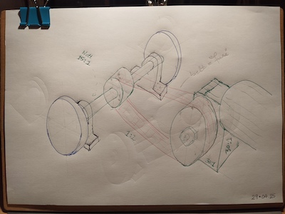
In brought-in ideas section "Cylinder/barrel/shell diameter and largest rod diameter" there is a sketch of a test dropping bars onto pieces of ore, getting an evidential suggestion of what feed-size the rod-mill with dimensions it has could take.
Advice-received section "20 March 2025 - expert says good" - managing expectations, I didn't say that the estimate was that a rod-mill with these dimensions could possibly take a feed-size of 15mm to 19mm.
I did that drop-bar test, as previously sketched, today.
Dropping the bar onto two equal-in-size crushed granite chippings,
positioned to be at each end
[The "120mm drop" is ((220dia-40dia) * 2/3 "cateracting height")]
It seems the expert's estimate of what the rod-mill being made would handle as a feed size, at 15mm to 19mm, is accurate.
Progress made.
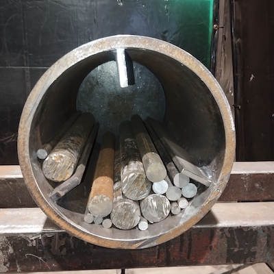
Trying to follow "expert's" advice on completing the initial rod charge:
The mass (weight) of rods seen in the picture is estimated as being 24kg (from size, number and density of steel).
Also per advice are the "strakes" to carry the rods and and ore charge
around the mill as the shell rotates.
As seen in the pictures.
I have concern that the strakes at 40mm tall are too tall in such a
small shell.
Choosing 3 strakes at about 120degrees apart is in the hope that
cataracting rods and charge land between the two strakes on the
opposite, lower, side of the shell.
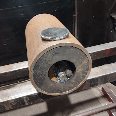
The far end of the mill as-seen has a flat disk welded in-place; a full circumferential weld to seal the contents in.
The front cover as-seen could be welded inside the shell.
If initial tests are on granite chippings of no significant value, it
may be possible to not insert with central cover, maybe tolerating
some spillage of the charge, in order to observe the grinding action.
Seeking to optimise the rotational speed on qualitative observations.
Seeking ideas for a drive to a rod-mill / tumbling-mill (a "shell" / "barrel" could contain grinding balls for a ball-mill).
We already know from calculation above that rotation speed needed is around 60 revs per minute.
Going for this idea - the "barrel" sits in-gravity on two rollers
which rotate (one driven and one free-rotating?). Therefore the
"barrel" can be lifted on and off at will. Plus alternative barrels
could be put on the rollers.
Thought is to pick steel tube size for the rollers for which a polymer
tube size is found. To form "tyres" at intervals along their length.

05 May 2025 - Disregard this section. The readiness and economy with which speed control can be exercised by power-electronics subsequently came into view.
For this improvised setup - flat belts over maybe wooden pulleys?
Something like this?

Second countershaft?
Good guidance might be offered here, on YouTube:
"Molino californiano o de pisones"
Edgar Villavicencio
(are California stamps)
Currently on YouTube
here.
They use 2 countershafts - hence 3 stage speed reduction - from a
"Honda GX(?)" petrol/gasoline motor to the California stamps. Using
flat-belts.
The likeness is
If these folk, presumably very practical and experienced, from an area with a lot of experience of mining and mineral processing, used to economical solutions in a low-income (?) area, see multiple countershafts running flat-belts as the best solution - it is unlikely there is a better economical solution.
Take "drop" of rods and charge as being 120mm - as previously mentioned.
An energy calculation is: all charge - rods and mineral - through
120mm 180X per minute, as rotation is once per second, and 3
paddles mean 3 "drops" per rotation.
(the approximation is: not all the rods and mineral will be picked up
by the "paddles"/"strakes" each time they pass the lowest point of
the shell rotation - which would reduce the actual power needed below
this calculated power)
"Potential energy" of a mass in gravity
E_p=m.g.h
Mass of mineral charge - take density as 3000kg.m^3 as has metallic mineral in it (so greater than 2700kg.m^3 of silicious rock)
Take that a 100mm x 100mm by 400mm long "cuboid" of mineral is mineral charge
(* 0.1 0.1 0.4 3000) ;; 12.000000000000004So that's 12kg.
(*
 (+ 24 12) ;; 36 ;; kg rod&mineral charge
 9.81 ;; gravity ;; N.kg^-1
 120e-3 ;; rise-height
 (*
  1 ;; revs per second
  3 ;; paddles lifts per rev
  ) ;; 3 ;; "lifts" per second
 ) ;; 127.13760000000002
So that's 127W of power drawn by what's happening within the shell of the rod-mill.
Another "take" - put the entire mass at the 3o'clock/9o'clock position
and calculate what that would mean as a power.
This looks to be the "Laws of the Universe" absolute upper limit to
what's happening in the "shell" could possibly draw as a power...
(*
 (* 220e-3 pi) ;; 0.6911503837897545 ;; m.s^-1 rise-rate
 1 ;; rev per second
 (* (+ 24 12) 9.81) ;; 353.16 ;; N
 ) ;; 244.0866695391897
Would be 244W
The 120mm "lift" giving 127W of power is the more credible.
The "most it could possibly be" "backstops" the calculation of 127W.
Is an independent check the 127W is plausible.
Put that up to 175W to allow for maybe eg a larger-diameter
barrel on the rollers, faster rotational speed if eg have a
"barrel" as a ball-mill, etc
As commonly thought of, 175W is 1/4HP ("horsepower").
Another instinctive adjustment factor says double it to allow for
friction and losses in the drive, suggesting a drive-motor (electric
motor?) power of 1/2HP.
Given what was demonstrated to me on the 18th of April - a rotating welding positioner. Which has essentially the same mechanics as would work for the rod-mill...
Equipment assembled so far:
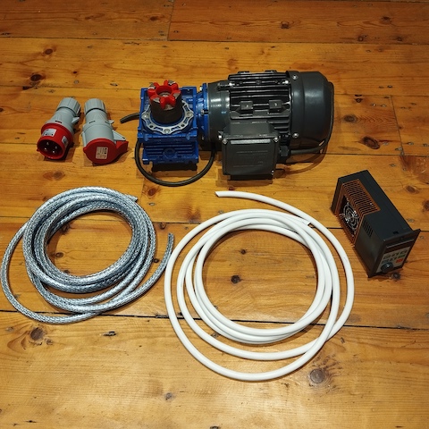
In-outline, the drive goes:
"mains" 1-phase electricity at 230V, 50Hz (the British norm)
v
1-phase to 3-phase variable output frequency "inverter" converter
v
3-phase motor
v
gearbox - speed-reduction - worm-drive
v
mill wheel-drive
The significance of the "inverter" (look up should lead to "IGBT's") converter - the "VFD" (variable frequency drive) - is that it "chops-up" 3 outputs off its internal DC (direct current) "bus", "square-edged", at 120degrees / 1/3rd-cycle apart - ie. it synthesises 3-phase which is fine for a 3-phase "induction" motor. A 3-phase induction motor is self-starting, self-running - and its rotational speed is in proportion to the frequency of the electric input. Hence - instruct the VFD to change the "chopping-up" frequency of its output and the 3-phase induction motor will follow in proportion with the rotational speed on its rotor and therefore output shaft.
Not 1-phase ("single-phase") motor?
Drive-wheels can be from some heavy-duty castors I have been gifted.
Beauty of this arrangement is that
"direct drive" - need 15:1 gearbox.
Need "new" gearbox - but neat simple arrangement.
Does need keyway machined in middle of shaft with the powered wheels.
As cannot see an easy way to power through end of shaft which has nuts
for clamping the drive-wheels in place (?)
"indirect through one belt" drive using existing 30:1 gearbox.
Final drive at 1:2 speed increase with flat belt.
Pulley on driven-wheels shaft is the smaller speed-increasing pulley -
smaller size giving more clearance to drum
Keep motor and gearbox away from dust, spillages, dropped and
trapped things, etc.
Could get motor and gearbox even further clear by locating well to the
side, with board between it and shell region - hole through for 30:1
drive-shaft - then needing one more plumber-block to support the far
end of that shaft (likely very desirable if do wet milling - which is
likely to be on the metallurgical outcomes investigation paths).
Flat-belt drive forms a mechanical "fuse" - would break first if
jam-up and readily replaceable.
If these topics are of interest, you can use this Contact Form to send me your contact details. We can then correspond along this established link.
(R. Smith,
18Mar2025,
19Mar2025 (eds),
20Mar2025 (expert,
mech,
pic2posn),
23Mar2025 (eds. inc. "cataract"; rod>ball opt.),
24Mar2025
(tests,
barrel),
28Mar2025 (corr. rock break size),
06Apr2025 (drive),
07Apr2025 (str.pg. w. "names"; correct "lifts" power; many local edits),
08Apr2025 (cont.fm),
05 May 2025 (mech.dr.>sm.txt.; VFD drive eqt),
07 May 2025 (mech.arrange ex VFD)
)