Serves "seeing is understanding".
Mainly
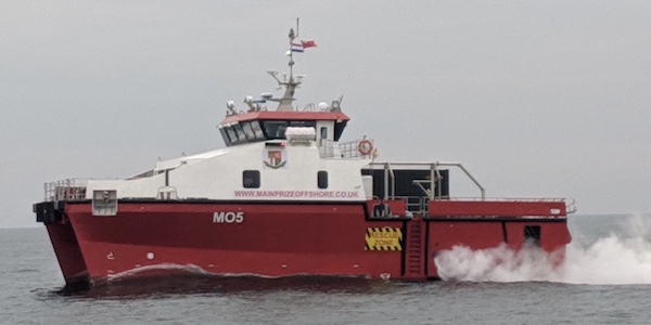
Is marine.
Provided a solution they didn't known was needed but were glad they
got.
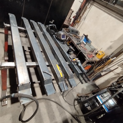
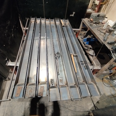
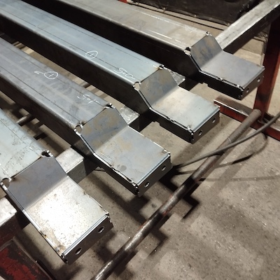
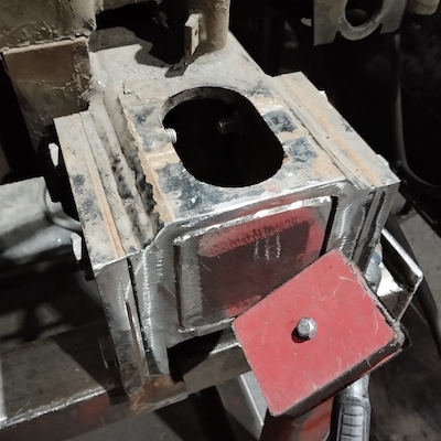
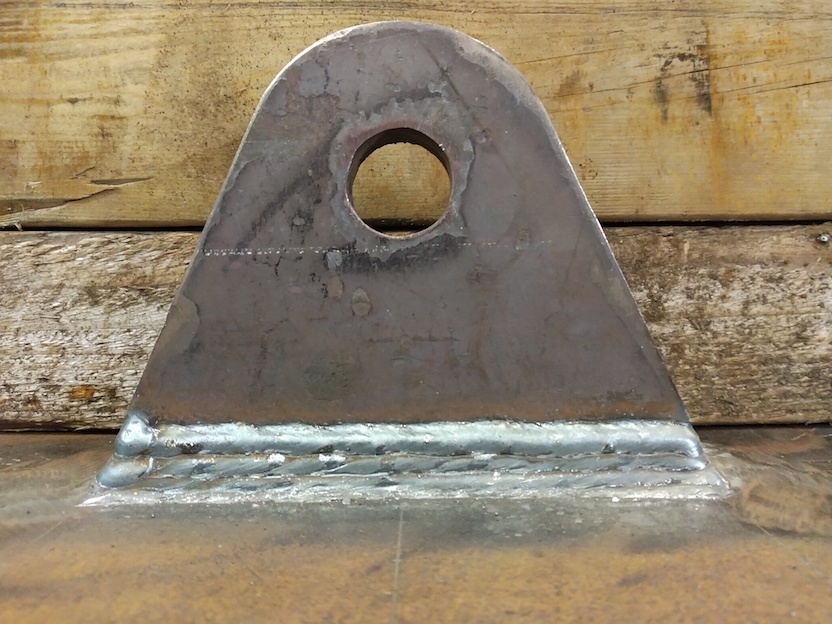
Seen in the first stage of fabrication:
The main structure is a "U" channel, 5mm thickness plate "profiled"
and press-brake'd.
The "notched" end-regions take a bent plate inserted, as seen.
The "channel" serves as a strut (imposes a longitudinal distance) and a beam (takes loads "normal" (at right-angles to) the length dimension).
The crucial issue in fabricating and welding this component: the
"channel" pressing would have to be something like 1-in-2000 parts
accurate for the fabrication to fit-together per the drawing taken
literally.
Not achievable.
A press-brake accurate enough to make the "channel" fabricating
"literally as per drawing" would repay over 100's of thousands of the
components. The production run is in the high hundreds.
Hence the welder intervening, mainly applying spirit-levels, to get
the design intent, is the most economic solution.
That time is roughly about 15 minutes per component.
Another point: this component seemingly takes far too much work for what it is. However, its form simplifies everything else about the structure's design.
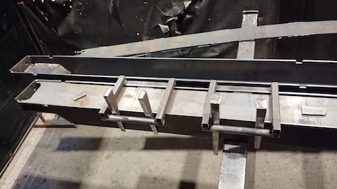
Fitting the "insert plates" with the 135degree fold:
Mark-up used during the welder intervention:
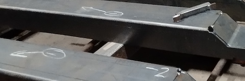
Both marking-up the results of applying spirit-levels
Another advantage gained by these interventions is no pressings
discarded to scrap.
This component cannot be seen in-service, so within structural bounds
there there is no issue doing significant corrections.
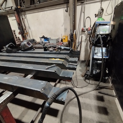
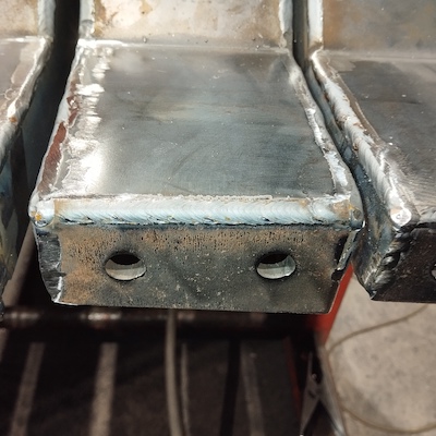
Fit the bolting-surface end-plates:
A "jig"; the long square with the two plates gauging the corrent
separation of the end-plates, is seen on the far left-hand-side.
After the interventions / corrections applied at the first stage, the
"jig" placement and the fit of the end-plates is "literal" - the
fabrication is the ideal simplest case.
A spirit level is again used in a way not shown: by an intervening correction to make the end-plates "vertical". The correction being applied with a large adjustable spanner slightly bending the tack-welds. Transverse squareness was accurately given by the "jig". No reference surface was accurate enough to act as a reference for using a square. The "jig" is checked by putting it on its side on a flat surface and using a spirit-level looking for verticals on its end-plates.
A lot of welding. Various conditions: "spray" and "dip" using GMAW/MIG.
Example weld - "dip-transfer" in this case.
These custom "wedge-clamps" were "leap-frogged" along the component. Squeeze-up the fit; weld made; clamp freed and moved ahead of the next clamp.
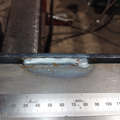
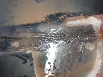
Example cover-plate to channel weld. Is along the length of tabs.
The weld is seen to have good fluidity and therfore fusion, as
evidenced by the brown "glass" on the surface of the weld. Without
excessive heat melting the edge of the "channel".
Repetitive but satisfying job.
The components unconditionally fitting during product assembly freed
effort to cosmetic aspects of the product for customer appeal.
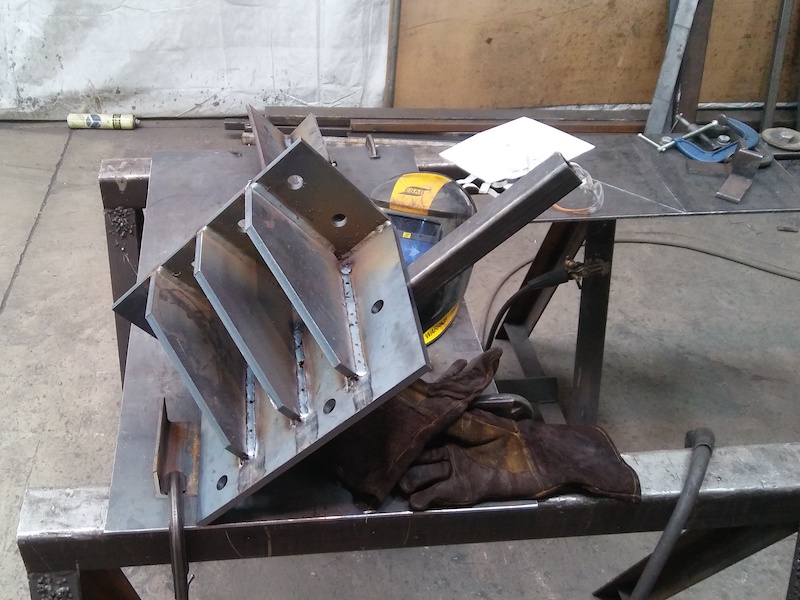
Minimum space, to the millimetre, was crucial in this case.
Hence - outside-corner weld end-cap not an option (would have added
another 8mm to width/length).
Not full-penetration - no engineering need - but assertive penetration, and groove enables directed powerful arc with surface tension holding fluid weld-pool.
Flushed-off after welding giving planar face along plane seen in this prep.
Machine parts.
No structural redundancy. However, in-service forces / stresses are
low. Also meaning dynamic stresses and fatigue resistance is a
limited issue. "Simply" - well-fused welds are "it".
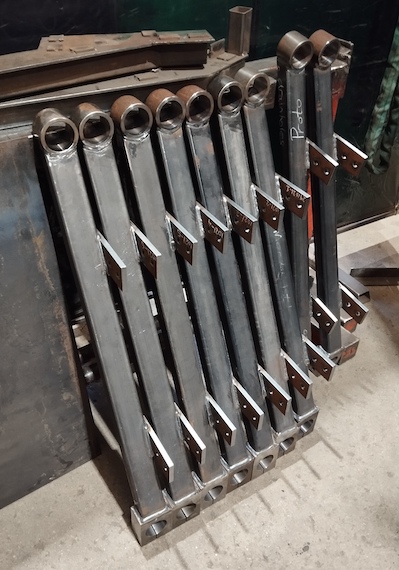
Weld "specification" was the prototype I offered - marked "Proto" as seen in picture.
Agency weld-fab'ing on and above deck fittings, the Foreman asked if I was confident to weld the hull. The painter found a weld pore, indeed proving full weld thickness when I ground it, and their welder was on-leave. I affirmed so.
The weld was in the "PE" position, vertically upward under the hull. Given
I selected "smallish" 3.2mm 7018 (calcium-carbonate based flux) rods, for the strategy
Result:
Asked by the Foreman if the weld is good, I asked he be the judge of that. He reappeared in 3 minutes - the time to walk down and under the boat and back to the wharf - and nodded.
Many in mineral processing in Cornwall worked on Hemerdon Hill and recognise these components. Great introduction.
GMAW / MIG.
Tilt at 45degrees puts these fillet welds in the "PA" (downward)
position. Which is very insensitive to the welding torch being
forced out of vertical by the space constraint between the
gusset-plates.
They are "outboard" plinths for bearings of the Hemerdon mill. Hence are subject to high dynamic loadings.
Quick "EXC2" full-penetration double bevel - GMAW / MIG
All marine.
I will be frank:
Work done - boat-building new-build example
(R. Smith, 07Aug2025 to 08Aug2025, 11Aug2025 (7018pe))