I improvised this solution and am pleased with it. The crux of the matter is that I have converted the "push" of a simple hydraulic cylinder into a "pull" needed for some purposes and situations in steel fabrication.
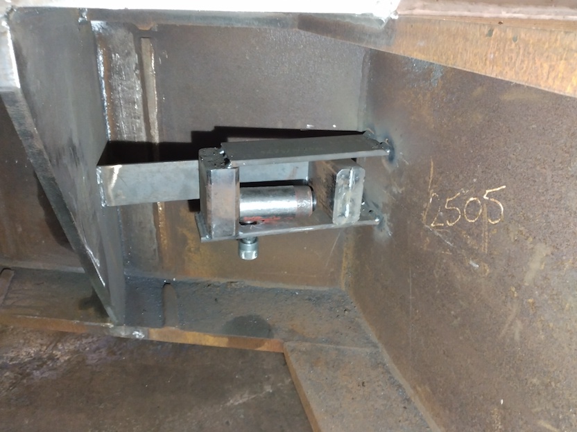
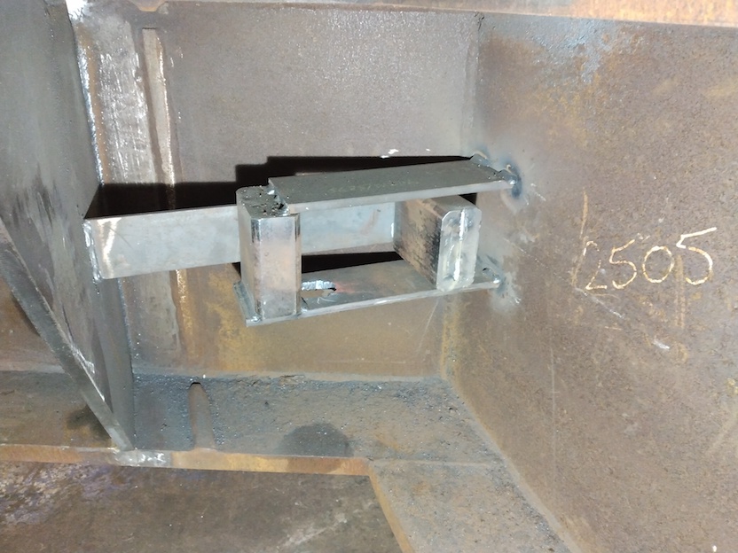
The rig's plate to the front has been cut-away, revealing what is inside.
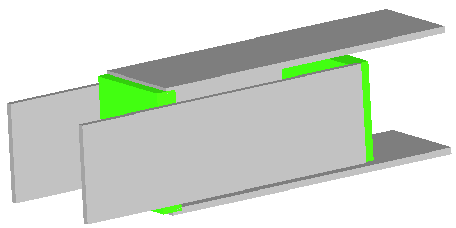
Complete, it looks as in drawing:
In use, a hydraulic hose from the hydraulic hand-pump runs into it.
Indication of size : the "end" beams of the "U"'s are 110mm long from 100x50 Rectangular Hollow Section.
This method is controlled, low-risk and predictable. With the force having easy application, variation and release at-will.
A simple hydraulic cylinder pushes.
This improvisation converts that into a pull.
The two opposing "U" frames, which interlock / "entangle" at 90degrees
(like the links of a chain), are temporarily welded to the two plates
respectively. The hydraulic cylinder is "trapped" between their two
"closed" ends, inside the four plates surrounding it. When the cylinder
is "pumped-up" and lengthens, the "interlocking U's" shorten.
That is the "push" converted to a "pull" drawing the plates together.
That "little" cylinder gives 10 Tonnes-force. These hand-pumped
hydraulic kits are formidable
A larger 20 Tonnes-force cylinder fits.
That the hydraulic cylinder is "trapped" in the arrangement is a
significant practical advantage, making the arrangement low-risk, as
the cylinder cannot "fly-out" if / as / when thing move with its
force.
Which is a potential hazard one has to be mindful of when improvising
ad hoc tasks with a hydraulic jack and the inevitable piles of
spacer-blocks. We are talking of many Tonnes-force here, with
significant potential energy stored in the plate deformations caused.
That "pull" is completely controllable. The steel-fabricator can freely work the pump handle to increase force, and turn the release-valve to reduce force.
On completion of the task, the temporary welds attaching the interlocking "U"'s to the plates are cut with a slitting disk in an angle-grinder. Releasing the rig. Then the remaining weld is dressed away with a grinding disk. Leaving no legacy of the rig ever having been there.
(R. Smith, 30Jan2021, 04Feb2021 (edited), 19Feb2021 (dwg U's))