These tests were made on 10mm diameter rope which is classified as "3-strand cut-film polypropylene rope". That is, it is the familiar blue "Builder's merchant" rope, regarded as "disposable" because it is very cheap to buy. It comes with no certification or claim of meeting any recognised National or International Standard.
This can be good rope to use because its cheapness means it can be replaced if any question-marks arise over damage or wear-and-tear. This needs to be weighed correctly in relation to guaranteed better properties of ropes of significant cost - several times that of "cut-film PP" rope.
So this testing program sought to know realistically the properties of this very commonly used rope.
Experiences working in steel construction started events leading to this program.
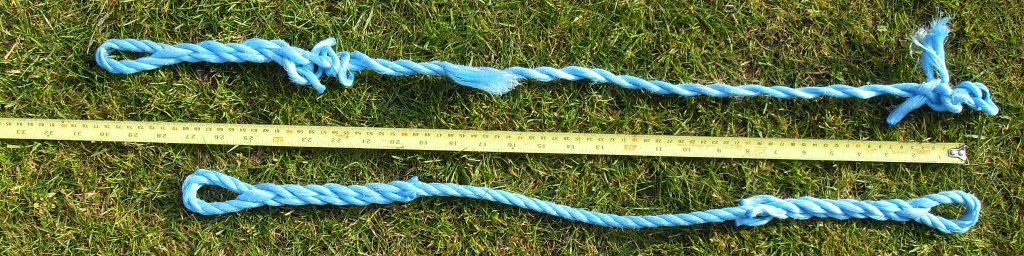
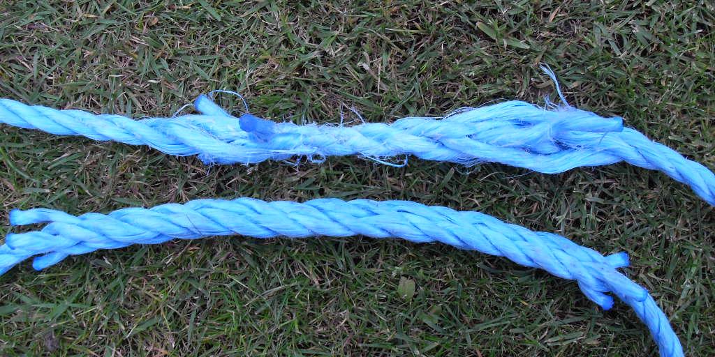
It was found that eye-splices give full-strength terminations. A simple length of rope breaks at the mid-length. This is seen in the following picture of a broken-in-test and an as-made sample. Elastic recoil of the strand which broke part unwinds the rope. However, the main reason for the messy appearance of the broken sample is run-on of the tensile testing machine after initial breakage. The sample was identical to its as-made appearance until breakage - apart from being stretched by more than 10% by this point.
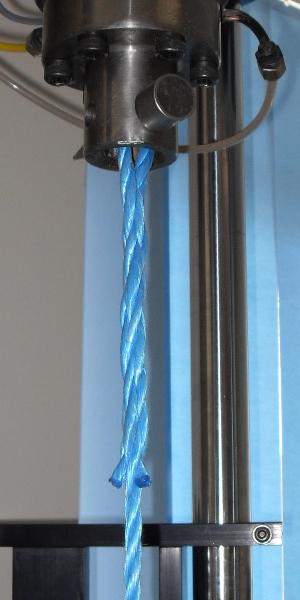
Mounting in the tensile tester by at each end pushing the "eye" up the grips-mounting socket and sliding the retaining pin through the eye of the splice proved ideal (picture of eye-splice termination in tensile tester). This maximised the available length for the test rope.
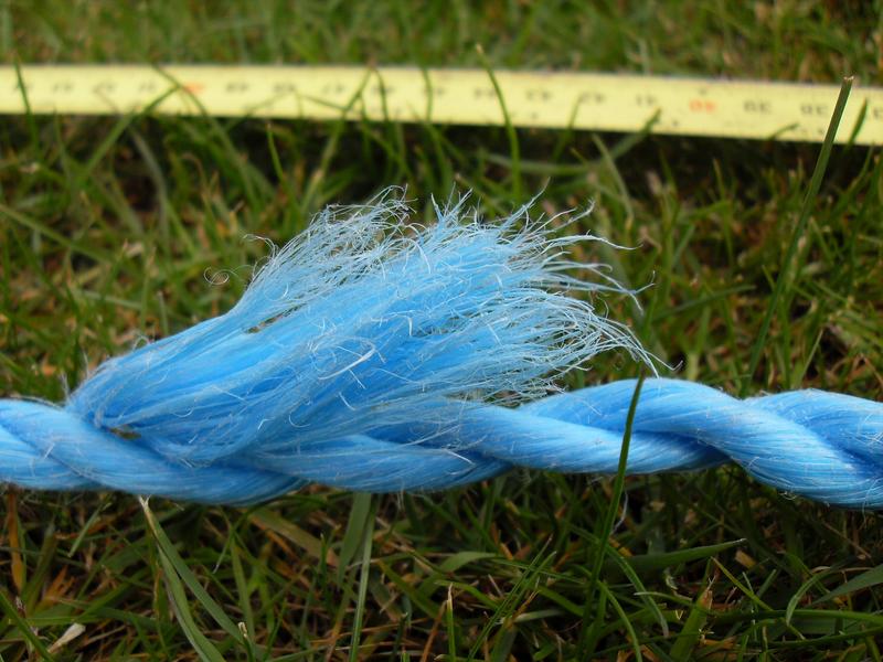
For a plain rope, fibre breakage started at clear over 90% of the ultimate tensile strength, rapidly becoming a continuous crackle approaching the moment of breakage. Here is the breakage point. There is an aroma of hot polymer on breakage.
The 12.7mm grip-retaining pins proved large enough to restrain this 10mm rope without loss of strength. The pressure of the rope on the pin was sufficient to weld fibres together.
Two tests done so far on a length of plain rope gave 13kN and 14.2kN of break strength.
What does that mean for lifting up objects? Well, 10N is to a very close approximation the downforce of 1kg in gravity, so that's 1.3Tonnes and 1.4Tonnes weight that these 10mm diameter ropes would have picked up! These are the published strengths of polypropylene rope, but seeing it believing and being awed!
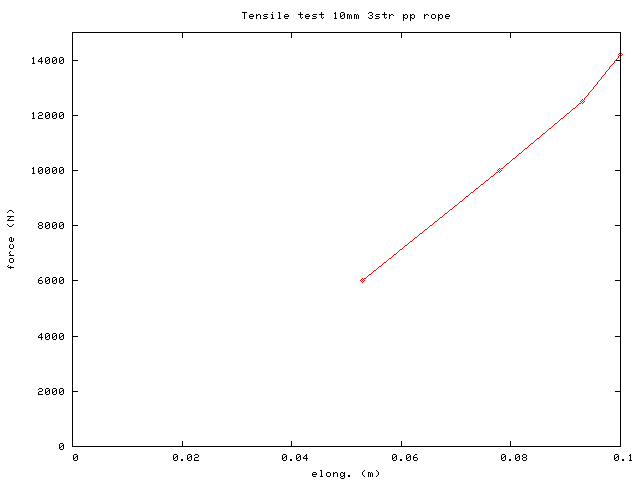
Originally 680mm between mounting centres, the rope has stretched about 100mm to around 780mm length at moment of breakage. To about 10% of ultimate breaking force there was a declining rate of elongation with increasing tensile force, then settling into a linear force-elongation relationship until breakage.
Here is a plot of some data points noted for the tensile test which gave 14.2kN of breaking force. That the rope appears to show more stiffness up from the penultimate to final point is difficult to explain! The graph on the testing machine screen did have a waver in this area but was essentially linear.
Calculation of strength-to-weight for this rope was made possible after weighing a sample length of it. The values calculated, in units N m / kg, showed that this rope has about 6~1/2X the tensile strength-to-weight of standard structural "S275" steel.
The values are
Things have moved forward - see next section
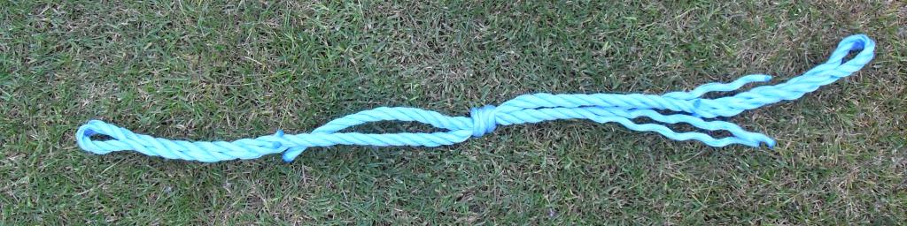
Settling-down of the splices and knots ran the tensile machine out of travel by the time a tensile force of around 7.5kN (about 750kg-f) was reached. This is still a high force and the knots and splices were warm with friction when handled on release.
The tightly squeezed appearance of these splices and knots pulled to 7.5kN tension is unfamiliar in any normal use of rope. The safety margins applied in practice for real construction site use mean you never (?) see such an appearance.
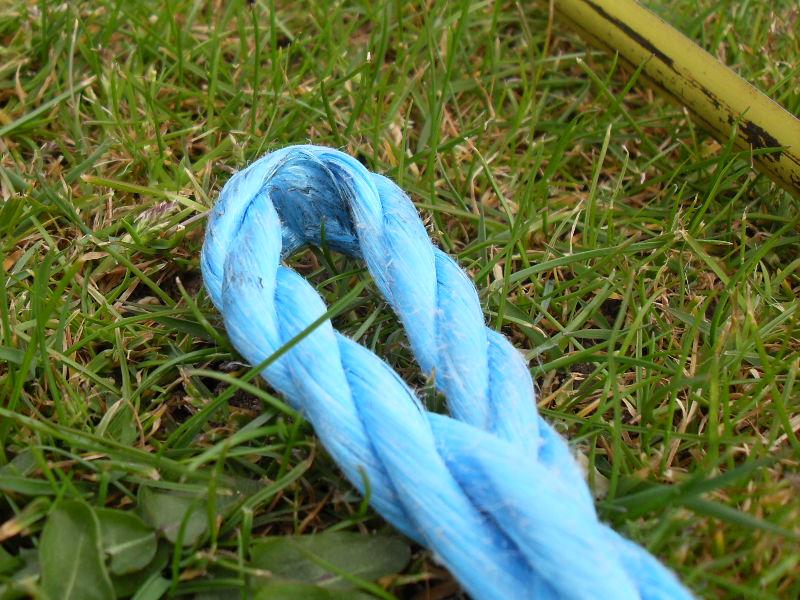
After and before testing appearances (although tested is 5 tucks vs 8 tucks for as-spliced)
Close-up of squeezed-up short-splice. Need to test if benefit from more tucks for slippery synthetic-fibre rope short-splices.

Fisherman's knot - tightly drawn up "as hard as iron" but still showing no sign of breakage.
These knots and splices were showing no sign of breaking. Even without knowing what force would be required to break them it is already proven that their strength even with this smaller than normally used rope is very high.
One of the terminating eyesplices was re-spliced shortening the Fisherman's Knot sample previously "conditioned" at 7.5kN
Tested, the sample broke at 9kN (900kg-f) - as seen in next image.
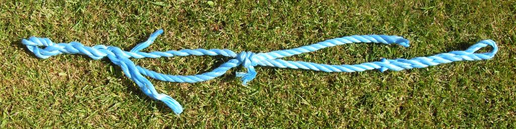
The breakage is at the knot, as can be seen. Which is expected, as knots are less strong than the rope they are tied in. Unexpected (at least to me) was the breaking force of 900kg-f - which seems a huge load. This Fisherman's Knot broke at 69% of the lower rope strength and 63% of higher rope strength previously measured. Literature typically quotes a Fisherman's knot as having 55% of the strength of the rope it is tied in. So my sample is performing usefully better than "book values" - for reasons not yet determined.
A lot of the reason for doing this page is to seek ideas and suggestions.
Someone said put in a disclaimer! Well, any sensible person would rightly tell you not to do or try any of this stuff here or just about anywhere on this site.
The initial idea is a machine which can be used to "condition" knots and splices before they are put in the tensile testing machine. Make them short, "draw-up" the knot or splice, pull out some of the initial stretch of the rope then transfer the "conditioned" sample to the tensile testing machine where the idea is that it will just fit between the crossheads at minimum initial separation.
However, looking into the future, whatever I do, a long-splice will never fit in a conventional tensile testing machine (because it's long!). Looking even further ahead... Because you do a long-splice so the splice can pass over sheaves ("pulleys") of block-and-tackle sets, you need a "dynamic" test. One involving the long-splice running under tension over sheaves. I can imagine making a rig with two single-sheave pulleys over which runs a single rope with its ends long-spliced into each other to form a strop (an endless loop of rope).
This "dynamic" testing was what I was thinking of when I started the "static" testing. Which has already proved so incredibly more fruitful, involving and rewarding than I could ever have imagined. The precision of the "tensile testing machine" has delivered its own unexpected benefits in illuminating fundamental behaviours. Ya never know unless you start that journey...
Anyway, designs involving screws and hydraulics to apply tension never quite worked-out. Nothing came together and started "of itself" discarding layer after layer of complexity.
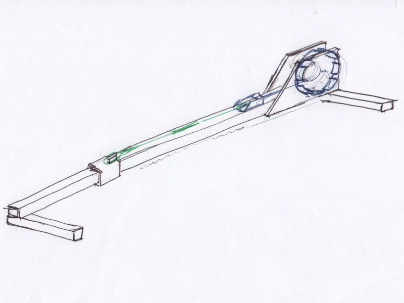
Then this type of design - scans of sketches follow - occurred to me. It is based on a Capstan or Windlass. This is more strictly based on a Windlass, as its "barrel" is horizontal in disposition and axis of rotation (a Capstan has a vertical barrel and axis of rotation). The principle is that the rope will grip a cylinder it is wrapped around when the cylinder is turned and something tries to resist the rope being drawn along by the rotation, even though the outboard end of the rope is free to unreel off the cylinder.
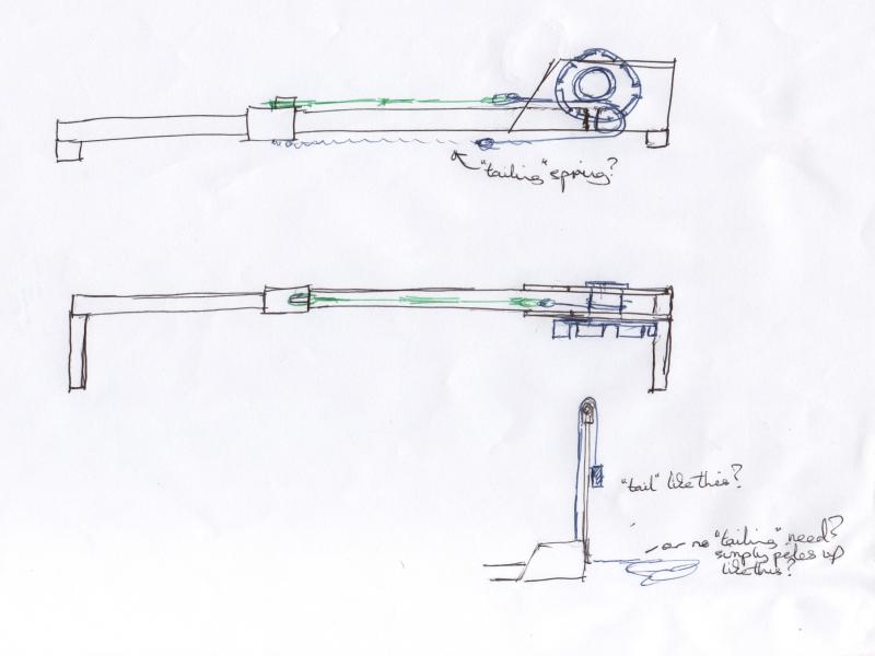
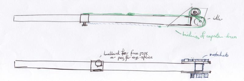
The leverage ratio is the cylinder radius to the length of what you are levering the windlass around with - which can be useful leverage ratios - maybe 40:1. And it's easy to make low-friction bearings for rotational motion, so mechanical advantage approaches the velocity ratio. Then, as if things can't get much better, a Windlass / Capstan device can apply that force uninterrupted over a large distance as the rope spools continuously over the barrel of the device.
Its likeness to a certain medieval machine only occurred to me a few days later! In plan it is much narrower than one of these machines but in elevation it is identical. The reason for independently arriving at a similar machine are the "first principles" fundamentals. Unless someone can come up with a concept that has completely escaped my mind, you are not lucked out with options that deliver a solution to this challenge.
The Windlass barrel is raised above the "bed" of the machine to reverse the direction the rope spools over the barrel. That makes the lever through the barrel end pull downwards as you stand beside the "bed" of the machine. Which holds the machine down against the floor. And allows you to swing off the lever to apply force. And as you know your body-weight, potentially you could know the force you are applying from how far along the lever you are gripping it!
Having worked on construction sites as a steel-erector, such logic is familiar when applying science to immediate work challenges.
I don't want to "start counting my chickens before they are hatched", but potentially for the dynamic testing you could leave a weight suspended on the lever arm to keep a constant tension while the tested long-splice forming a strop runs over an opposing pair of pulley-blocks.
R Smith, May 2009