Observation of a workplace lead to conjecturing this alternative
lifting equipment.
The "floor-loading" is so restrictive that any proprietary
counterbalance lift-truck uses-up just about all the load-bearing
capacity, and leaves a tiny payload.
Most applications can have the load within the wheelbase - unusual
but is the case in this application.
So here is what I ended up with.
It would have two fixed wheels at the front and a rotating powered
wheel at the back.
That power drive could be something like a "Honda GX-series" petrol /
gasoline engine, maybe with centrifugal clutch. The distances
travelled are trivial, and low weight of petrol wins over low per-hour
fuel consumption of diesel in this application...
The weight would be in the low 100's of kg, and free up most of the weight of a commercial counterbalance lift truck as "payload" for this lifting-frame.
For its application of lifting, a strop can be wrapped over the horizontal top beam at any location, supporting any generic hoist - eg a chain-block (manual or electric).
My "safety-case"
Explaining the latter point more:
this is a "non-destructive test" for a tubular structure which is
hermetically sealed with regard to the outside environment but
fully-cross-connects so all parts of the structure share the internal
pressure. Which is introduced through a valve similar to a
tyre-inflation-valve.
Typically drilled holes at necessary locations enable gas to flow
between the tubular members at welded intersections.
Pressurising a tubular structure is a fatigue-crack detection
technique used on aircraft with tubular lattice frames - in the USA on
"experimental" (home-made) planes and reputedly quite extensively in
the former Soviet Union and Eastern Europe.
Typically the pressure-gauge would be in the cockpit, and seeing a
positive pressure exists in the tubular structure is part of the
pre-flight checks.
This is a first-principles obvious method of warning if there is a through-thickness fatigue crack somewhere. It doesn't tell you where, but it has a 100% probability-of-detection of telling you if there is a through-thickness crack somewhere - irrespective of paint and coatings, location, accessibility, geometry, etc
The pressure would typically be something like 1Bar/1Atmosphere.
Obviously, knowing there must be a crack somewhere, the lifting-frame is immediately taken out of service, and whatever detection / inspection method(s) will find it are applied.
The possibility to use this technique of pressurisation as a fitness-for-service indicator comes from using Structural Hollow Sections for the entire structure.
These are SI units.
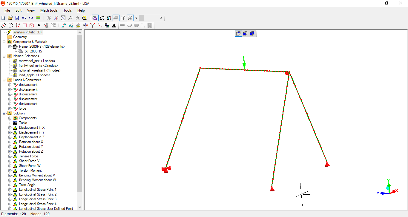
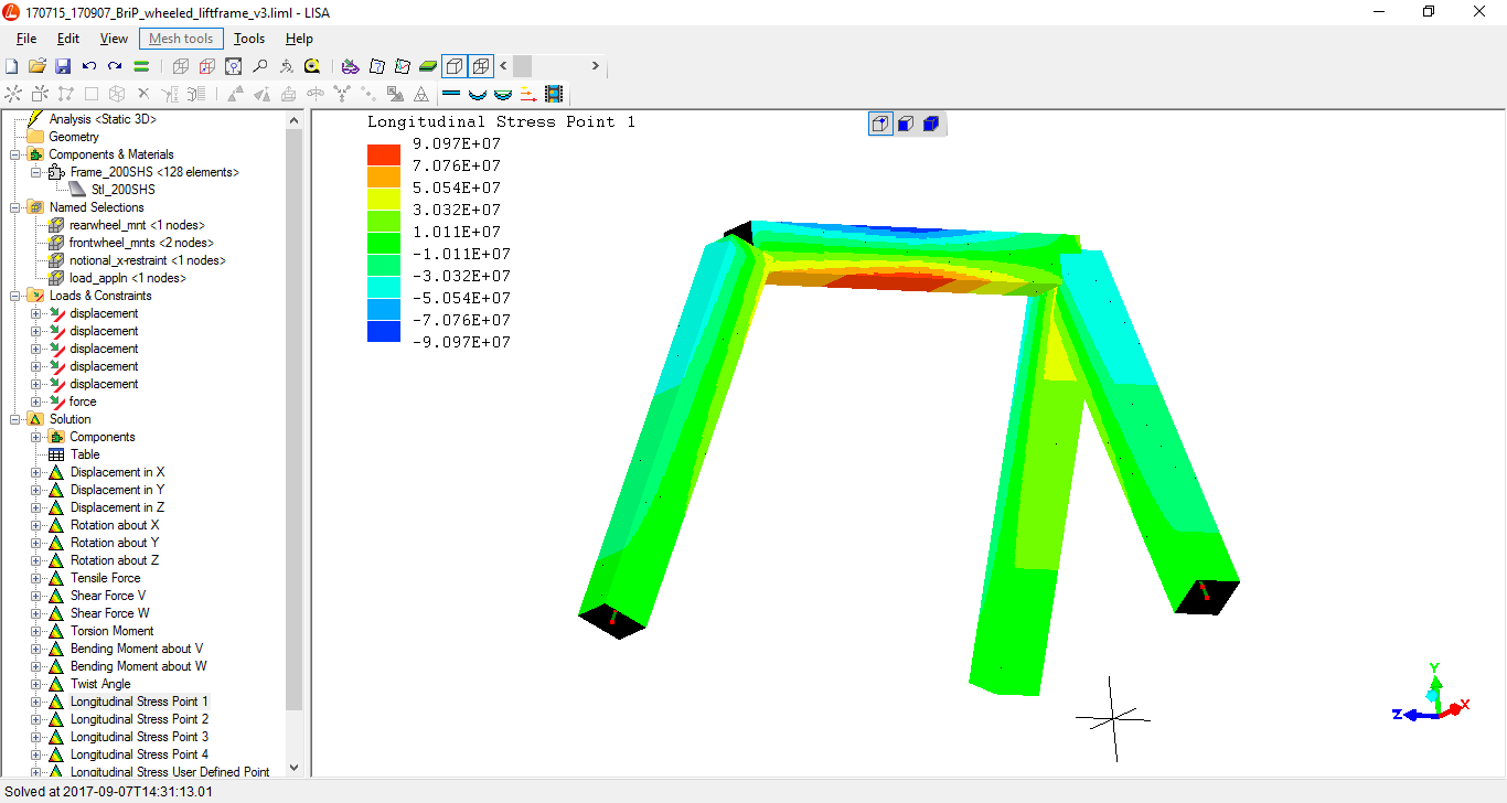
This line-element model prefectly well shows the overall stress-state
along the lengths of the tubular structurals.
The imposed loads and constraints can, and do here, exactly match and
represent the real loadings the lifting-frame is intended to bear
The imposed load here on the top-beam is 4.5Tonnes-force
(which is many times higher than the current payload with a
lift-truck(!))
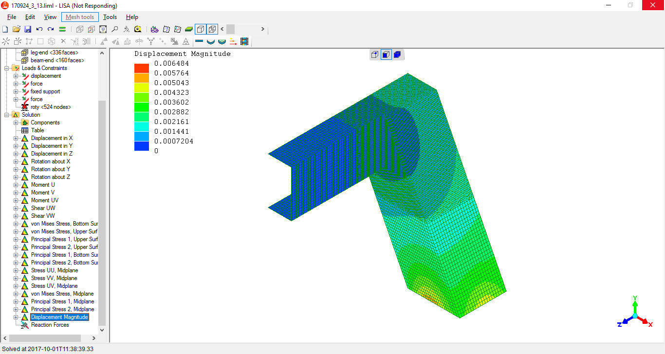
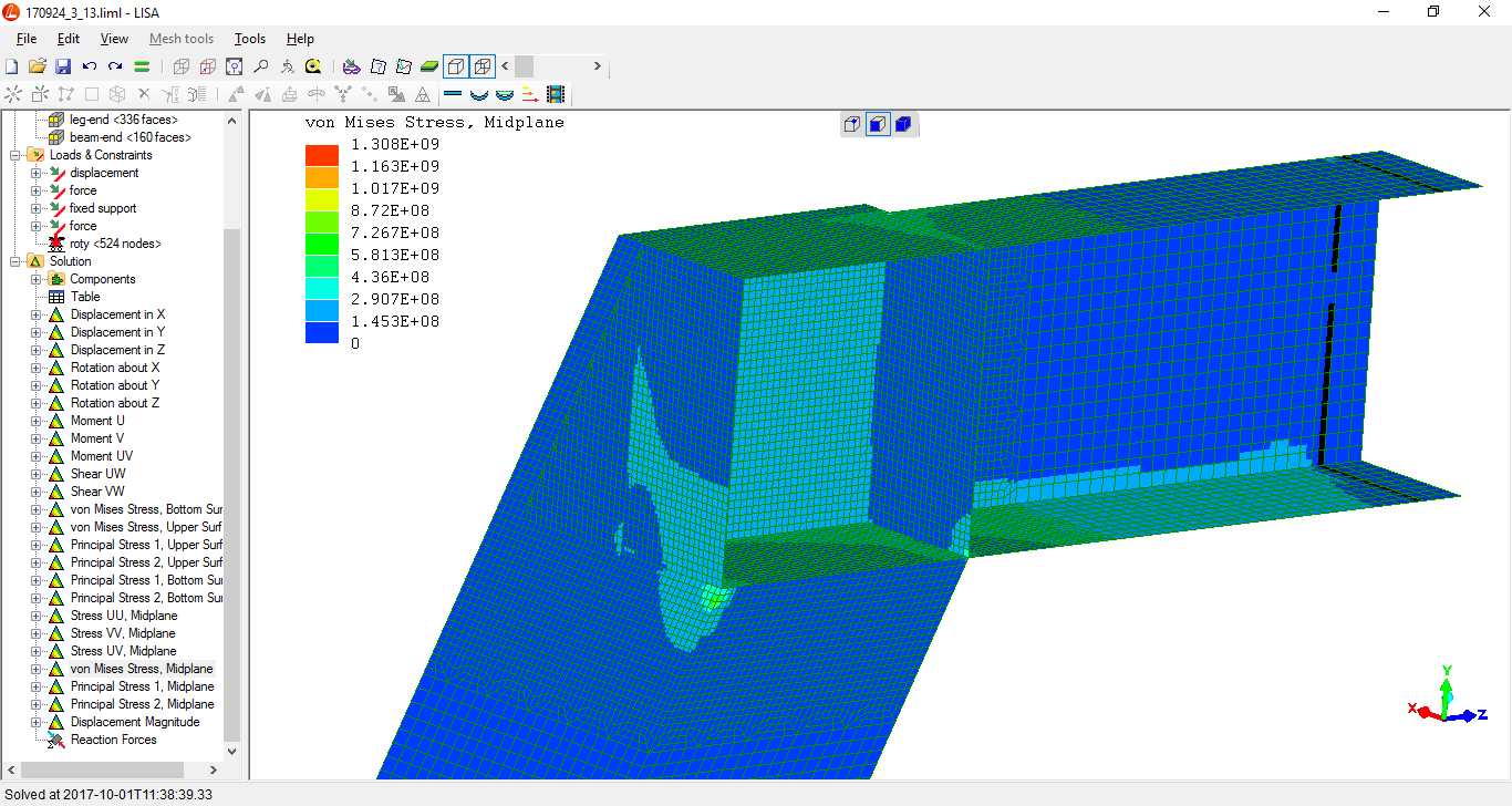
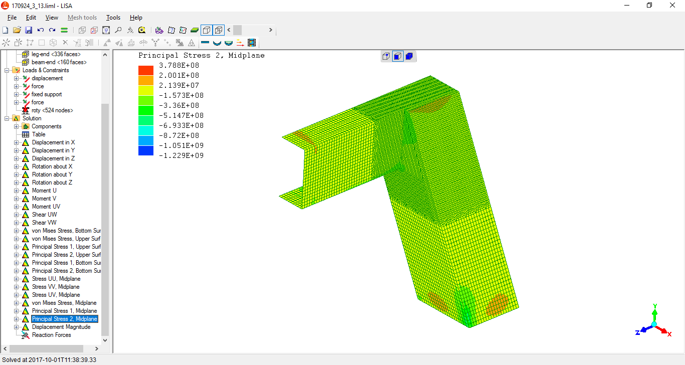
This complex computationally resource-intensive model has to detail solely the intersection area.
The finite element analysis model is a longitudinal half, as the
component has a longitudinal-vertical plane-of-symmetry, and
symmetrical loading is satisfactory.
Which enables a plane-of-symmetry to be applied in the finite element
analysis model. Halving computer resources.
By the way - this model took 8 minutes to run - about the maximum beyond which the resources required crashes my computer, and much more than the usual under-a-minute entire elegant solution times for my typical shell-element solutions.
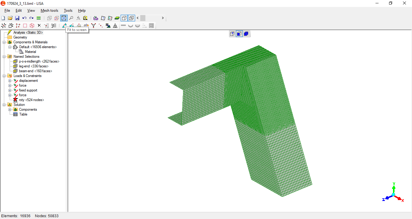
Meshing (fine!)
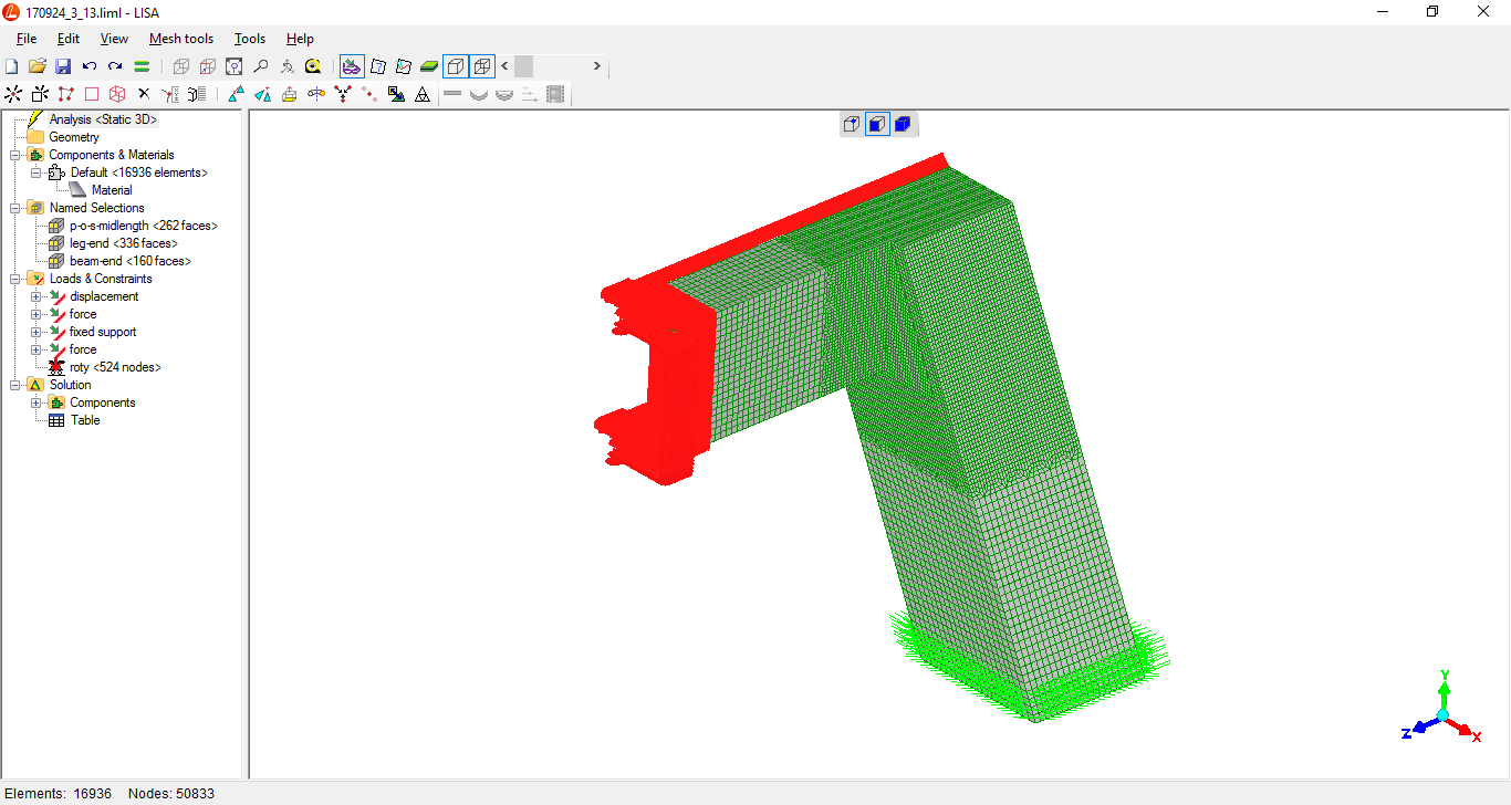
with loads (green arrows at lowest part of leg - 2 tonnes-force
rearward and sideways spreading the structure) and constraints (all
the red "stuff" - fixed support for beam-end and plane-of-symmetry
down axial centre)
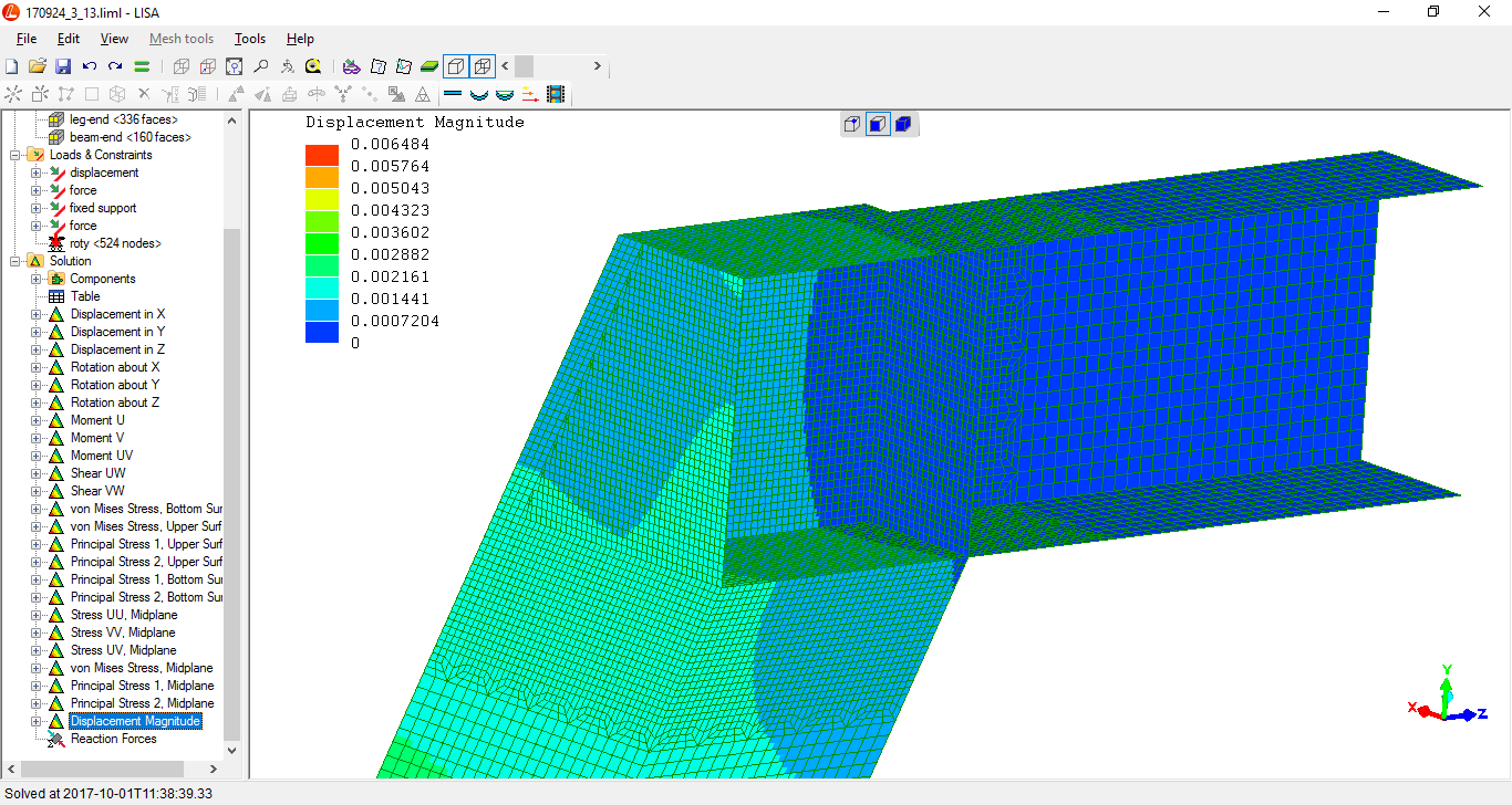
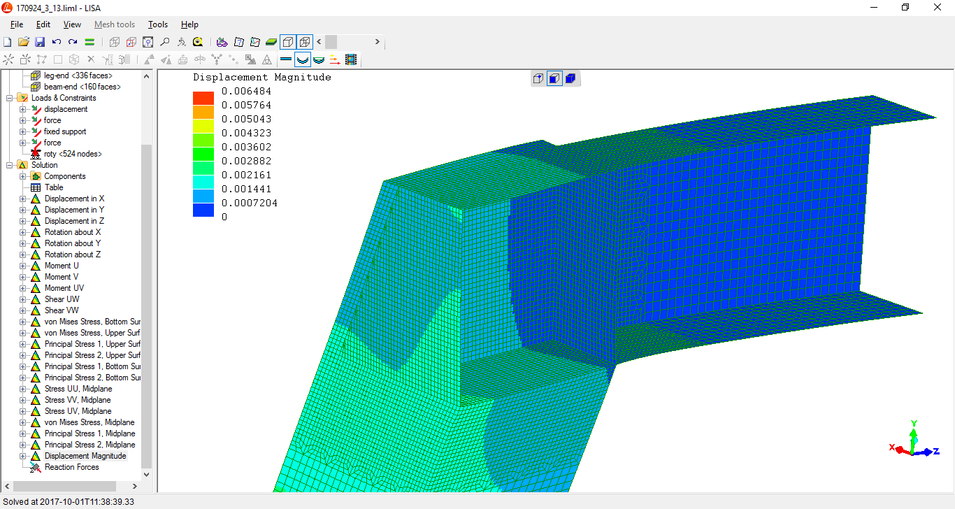
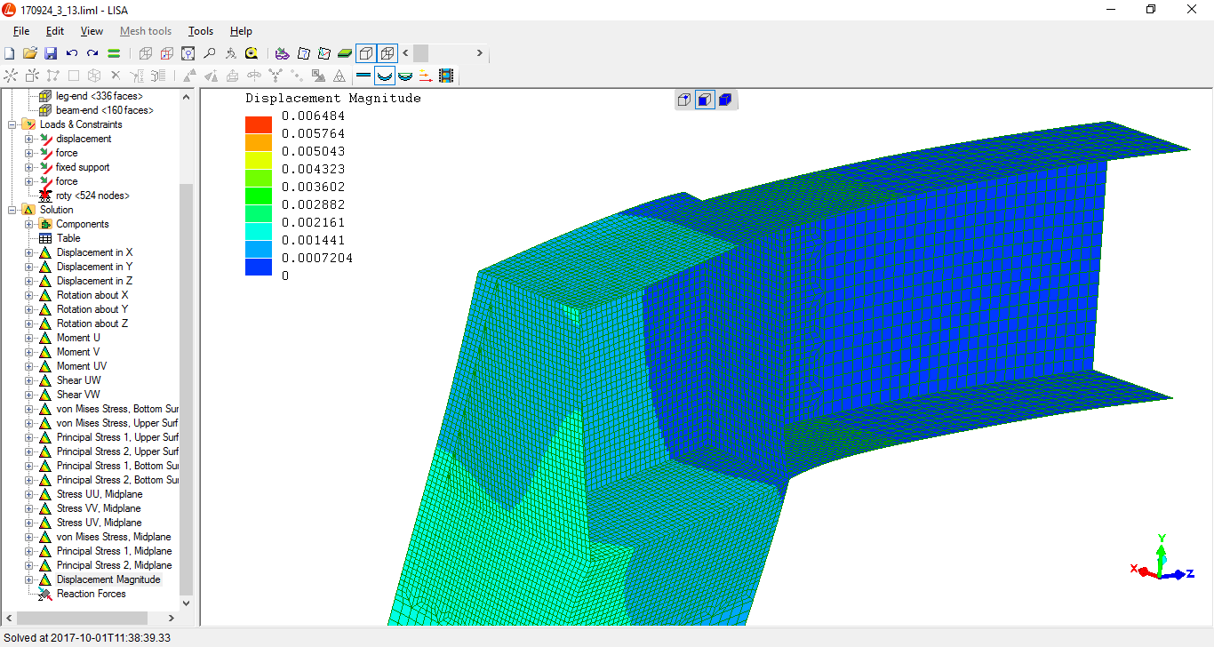
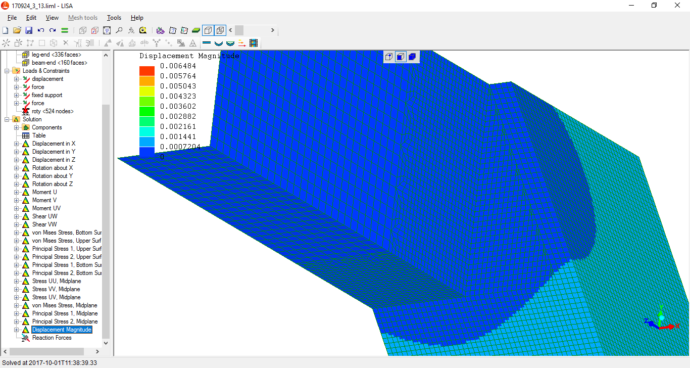
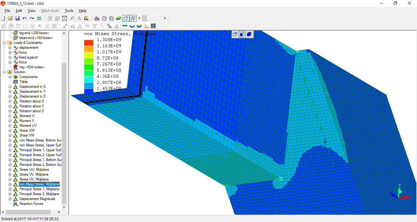
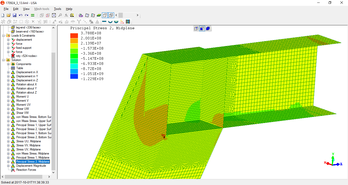
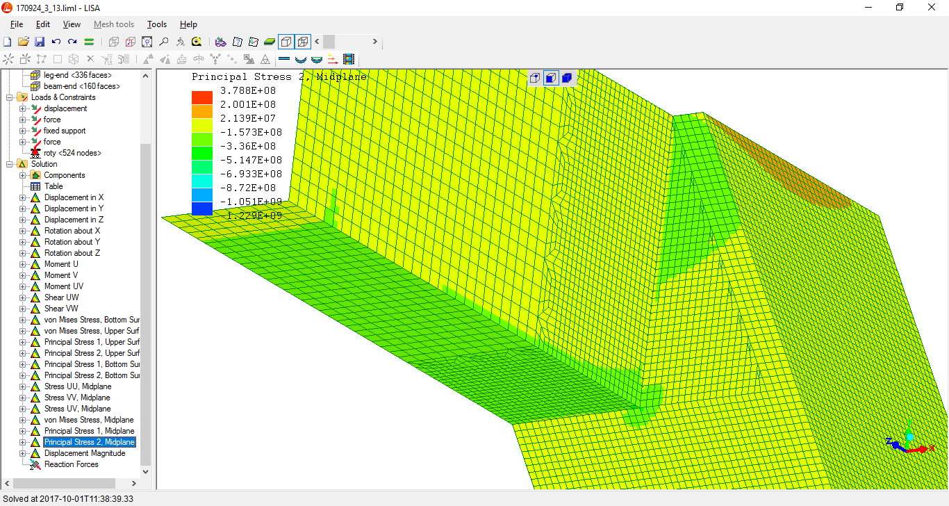
There are no localised elastic deformations at the intersection above the general levels of elastic deformation in the length of the tubulars (?).

deformation represented X24, with undeformed shape included
deformation represented X24
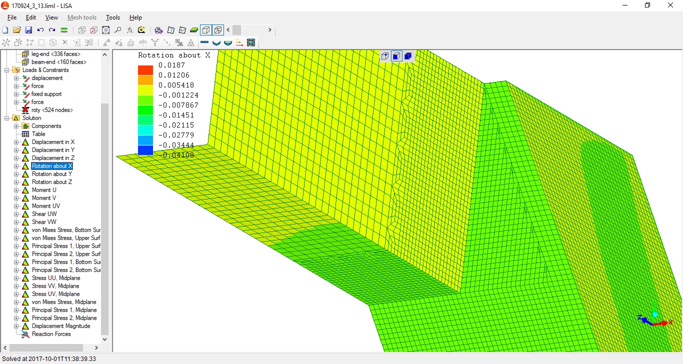
deformation represented X48
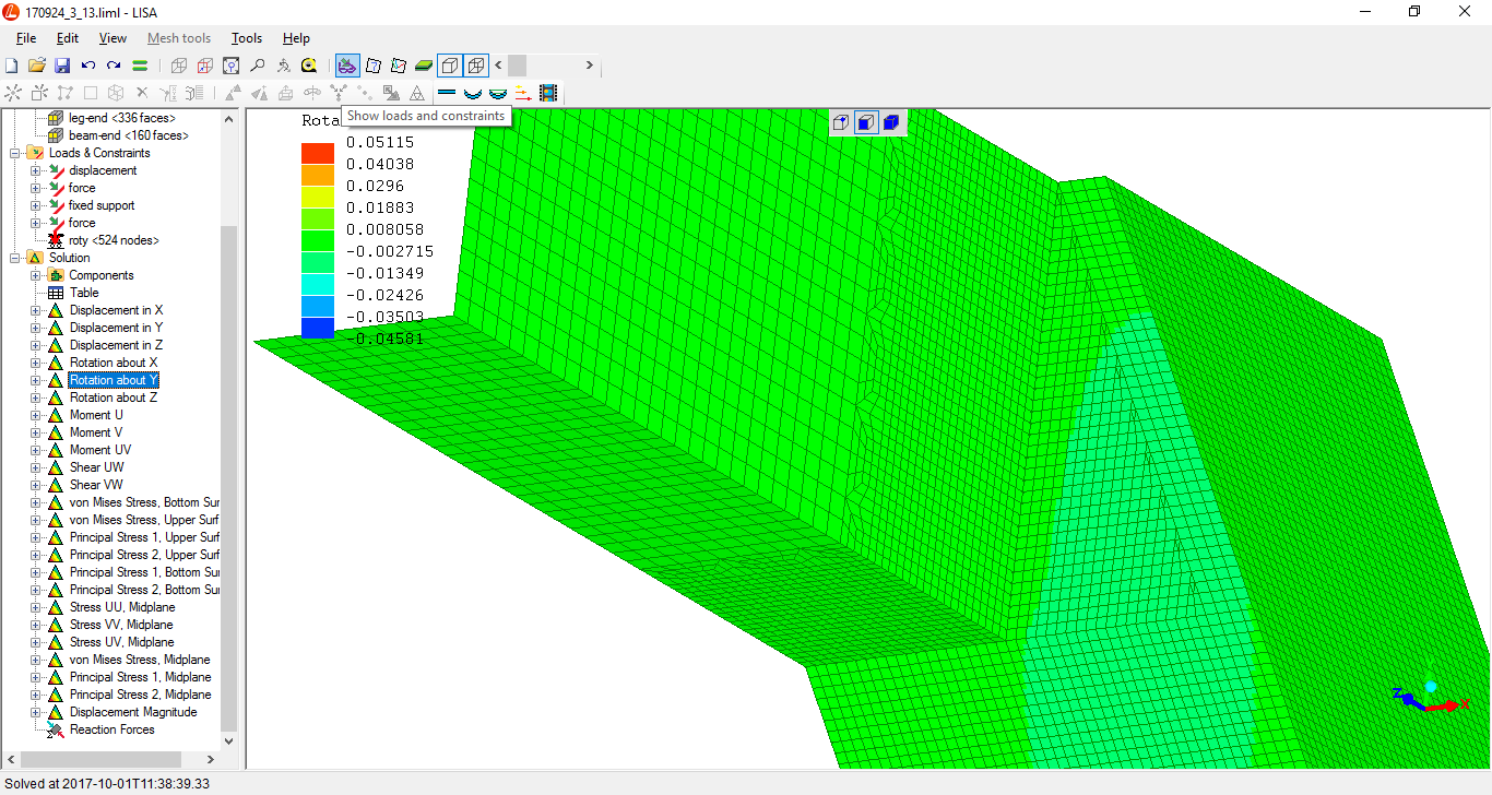
deformation expressed as rotations...
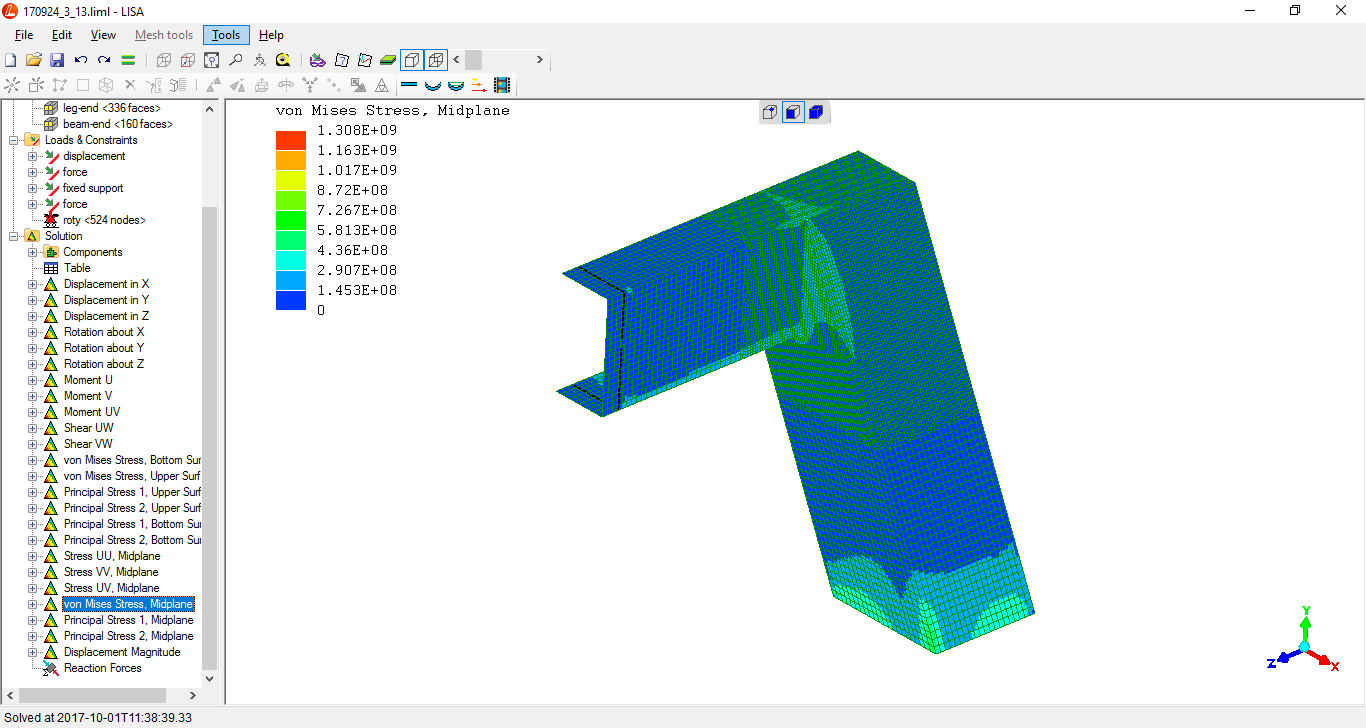
(there is no "principal stress 3" as this is shell-element)
"Principal stress 1"...
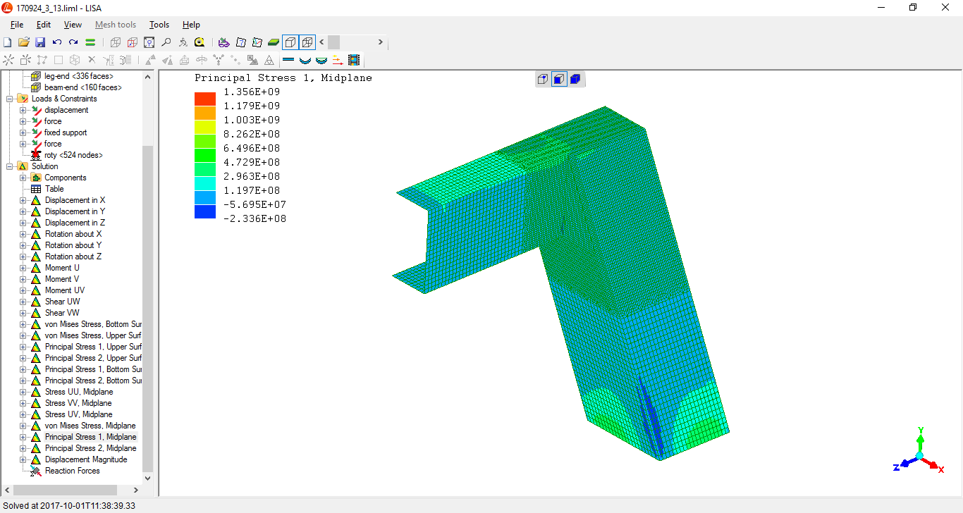
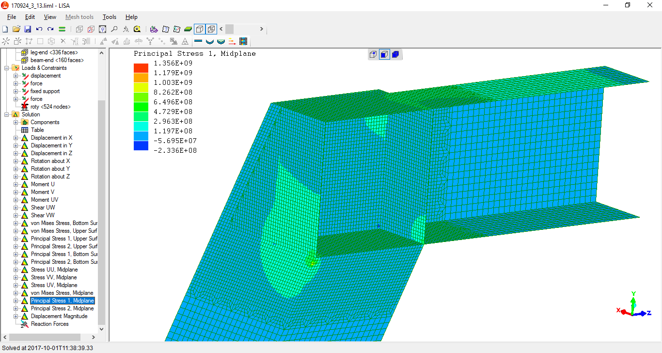
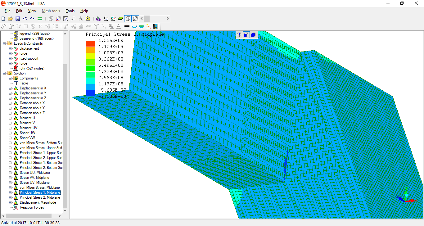
"Principal stress 2"...
(R. Smith, 01Oct2017, 03Nov2017)