I can hardly start to list why you should not take these simulations seriously.
Just look at the pictures for their "beauty" and think of what it
meant to me getting the program to respond in my first ventures away
from step-by-step tutorials.
There's quite a number of steps before the "solver" will accept your
model and produce a non-null output.
The "small steps" are happening...!
For what it's worth
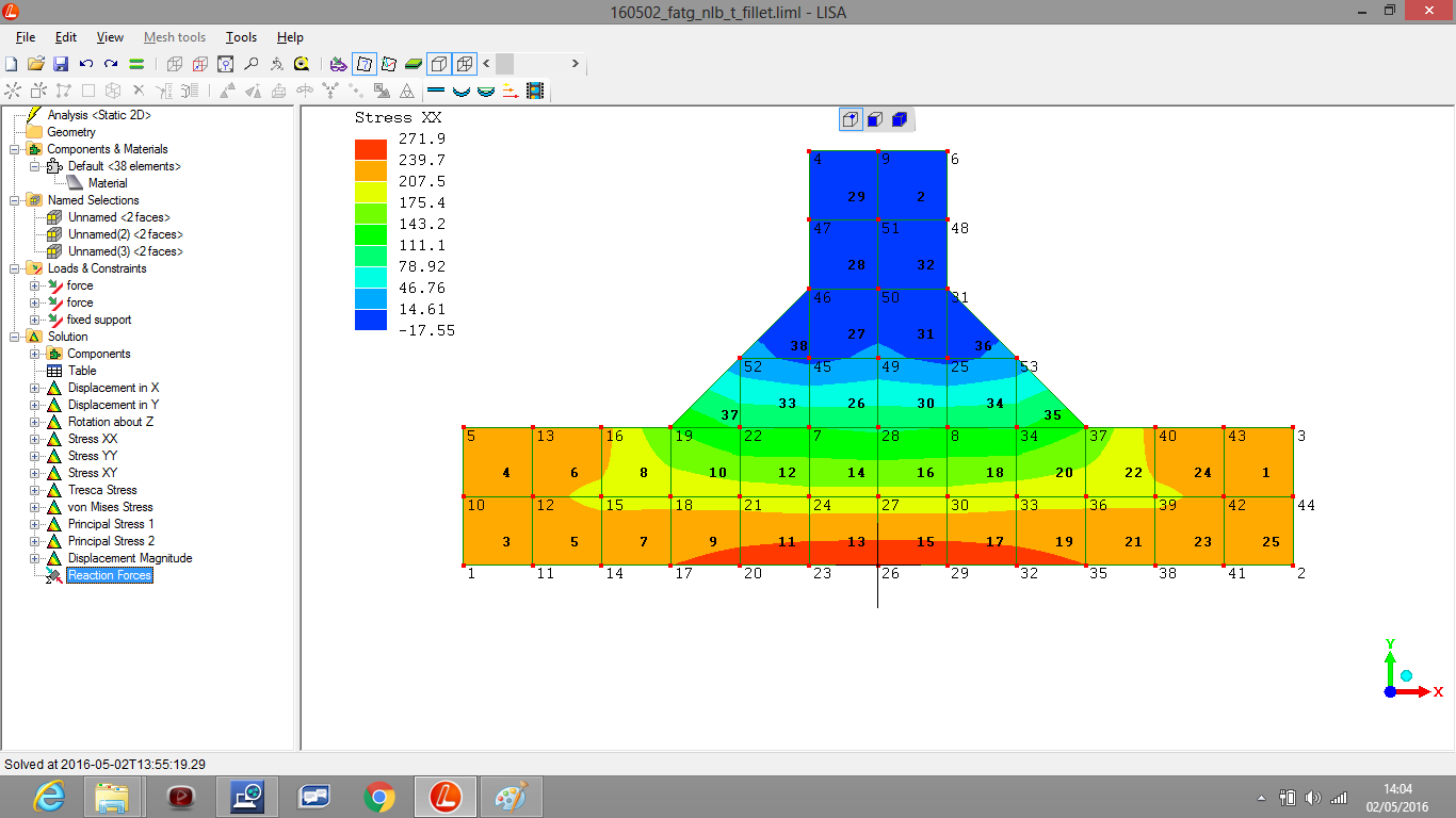
If there is an interesting thought from looking at this;
it's that the load is producing an bending away from the terminating /
intersecting plate, which is placing the unwelded side of the joint in
much higher tension while reducing the stresses near the weld. That
should be advantageous for fatigue-resistance - as fatigue failures
are mainly around welds. However - this observation does not match
what is seen in real life - welds fail by fatigue and one does not get
the impression that anything is "protecting" the weld from those
stresses.
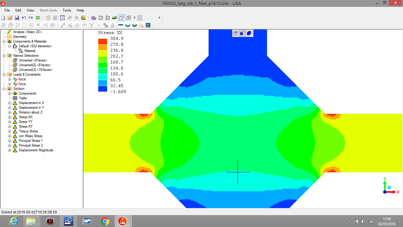
I've "cranked-up" the discretisation, making the finite-element mesh finer, for a more resolved, accurate, result.
I've "mirrored" the original weld, producing this entire "X"-joint
which is modelled in full. This form is balanced with zero bending
moment in relation to applied forces along the "main plates" (the
structural members reaching out left-and-right (hand sides)).
In order to just look at stress concentrations around the "fillet-weld
toe".
That's a very improvised way of getting around that I didn't yet know
how to create a plane-of-symmetry in a FEA model
(so it's as if the model had the "mirrored" part, for all its physical
effects - but you don't expend computer resources simulating it - so
you can concentrate your computing resources on the half which is
actually modelled)
Leave these for now and forget about them.
I'm trying to walk before I can crawl!
(R. Smith, 17May2016)