
Abbreviations used, and explanations:
I actually welded the structure as-designed without the stiffener plates.
Therefore, I observed its real characteristics.
My observations caused me to think of putting in the stiffener-plates;
which are familiar in structural steelwork using I-beams and H-columns.
A properly implemented FEA model of a structure, a representation in a
parallel world of numbers and physical laws, should show how the real
structure would behave.
Therefore if I "Finite Element" the beam-structure with
stiffener-plates added in the locations proposed, that should show
what this alternative structure would behave like if I welded in those
stiffener-plates.
How would the new structure perform? Would it be good? Would it be a worthwhile improvement over the current design?
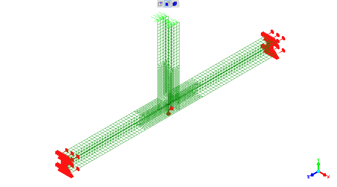
The FEA models for without and with stiffener-plates are identical apart from the with stiffener-plates model having these added (so that's like what you'd do to the real structure - you'd add (weld-in) the stiffener-plates).
I've shown each model both transparent with only the element edges
shown, and opaque showing element surfaces, so all details can be
picked-out.
It's not so easy actually see that they have / have-not got
stiffener-plates - as there's no colour variation here to make them
obvious!
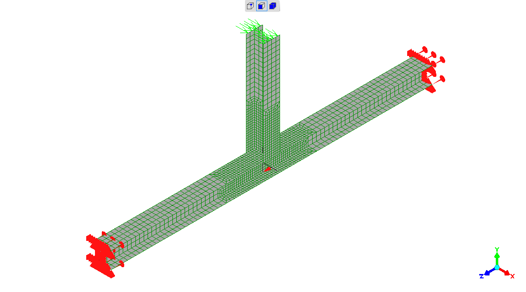

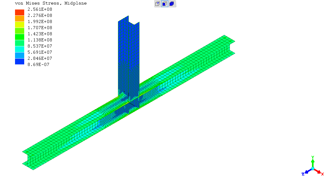
I've put 200kg-force sideways ("x-direction") on top of the column -
seen as the green arrows. So this produces a moment
("twisting-force", "torque") of 2000Nm in the horizontal beam.
A sideways 200kg-force at the top of the column is not large compared
to the weights of things being put on this structure!
The red clutter at the beam ends are: the beam-ends cannot move sideways ("x") or up/down ("y"), nor can they rotate (twist) about the beam-length ("z") axis.
However, the beam-ends can "pull-in" or "push-out" in the beam-length ("z") direction - which has a significant effect on the resulting stresses. Fully fixed is not realistic compared to what the structure can do in the real world. The conditions described match what can really happen.
The red markings in the middle, under the intersecting beam / column
are two restraints.
No movement in the up/down ("y") direction - as the structure is
sitting on the ground and weight upon it keeps there, regardless of
beam stiffness.
No movement in the beam-length ("z") direction approximates the
friction of the structure sitting on the ground keeping the structure
where you put it.
Humans are more more likely to think of "twist" in distance, like
millimetres. However, that doesn't well reveal "the story" with these
structures.
Think of twist as an angle, and display as such, then the structural
behavior jumps into view...
The twist about the long axis is quite localised to the junction.
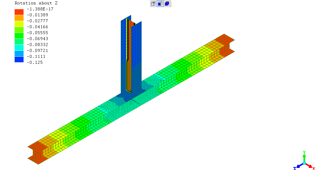
A significant part of the rotation of the column comes from a local event at the column's junction with the beam and along the top flange of the beam.
The "moment" in the column is produced by uniform elastic twist along
the intersected beam.
Which is as good as this overall design can give.
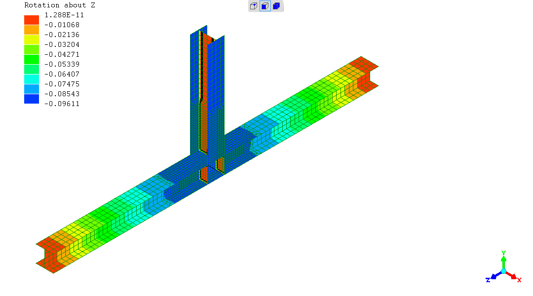
The moment ("torque") applied to the column passes into the beam without any local event at the junction - which is good.
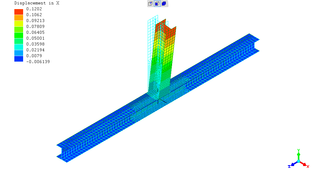

So the with-stiffener-plates structure doesn't deflect under load much
less than the current without-stiffener-plates version -
96mm vs 120mm, respectively.
Is that tolerable?
It will be seen that this is where the big difference is between the "without" and "with" cases, regarding a structural performance worth further consideration.
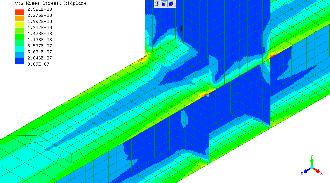
The stresses - are very high in the web of the intersected beam, just
under the intersection / junction. The simulation suggests that for
S275 structural steel, only 200kg of side-force at the top of the 1m
tall column (2000Nm "moment") would permanently deform the structure.
This prediction is compatible with what is seen with the real
structures.
Nothing much to see in the two top-views of the beam...
(though the stress scale hints there's something lurking out of view!).
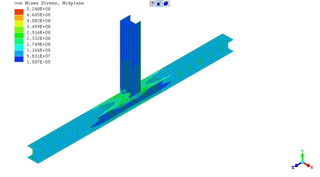
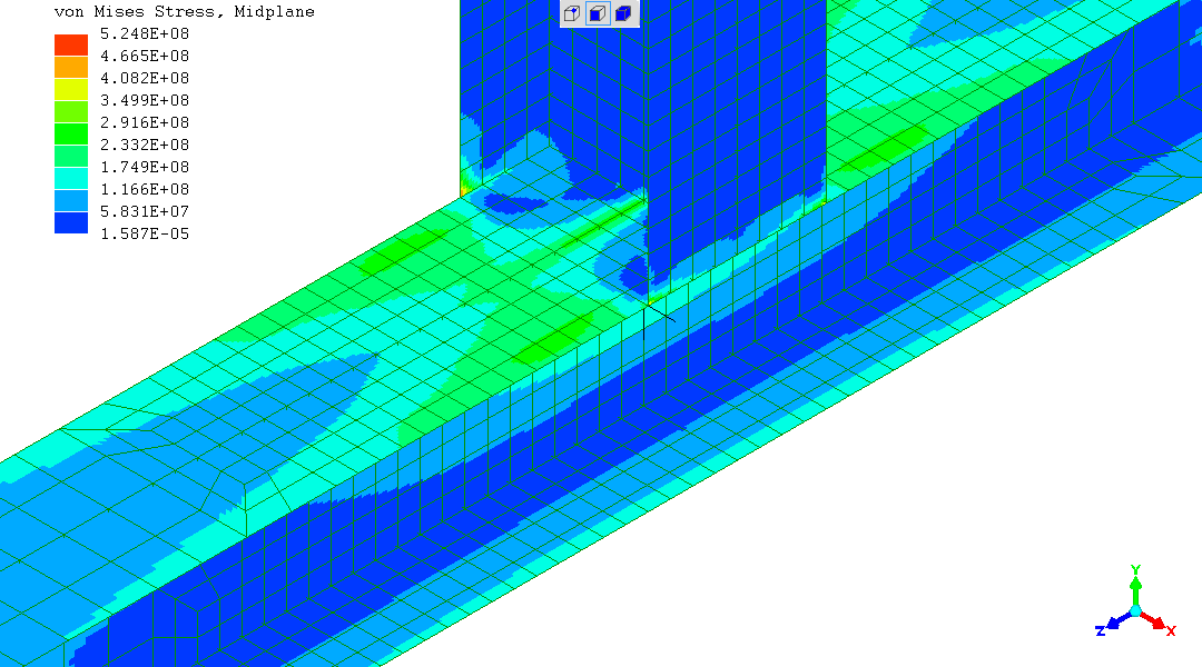
because the problem is all here - the high-stress region just under the junction...
The web of the intersected beam, the long horizontal beam, is grossly overloaded locally under the junction with the column.
The condition would cause plastic deformation.
Controlling the angle of the column, the plastic yielding here would
produce a big permanent lean on the column above.
Intuition based on other knowledge not provided by this FEA model
suggests this mode of undesirable behaviour is quite calamitous. As
there is nothing to make the load needed to increase the deformation
increase much, above and beyond the small side-load which set the
deformation going. That is; the resistance to continued yielding is
not likely to increase much (?).
(The author is thinking of the behaviour of "fully plastic" steel
sections which will not buckle with deformation in beam loading and
present increasing resistance to bending - as applied in "plastic
design" for buildings).
Stresses...
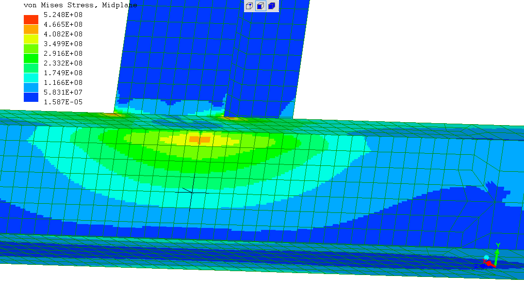
There is a stress "hotspot" in the four corners where the column meets
the beam.
That said, they are at half the peak stress appearing anywhere in the
"without" design.
The "hotspots" have appeared as a side-effect of the structure now
being suitably rigid.
We cannot really "go there" for several reasons
Nothing nasty hidden under here. All is well. Stress hotspot already seen on the top surface is also seen here...
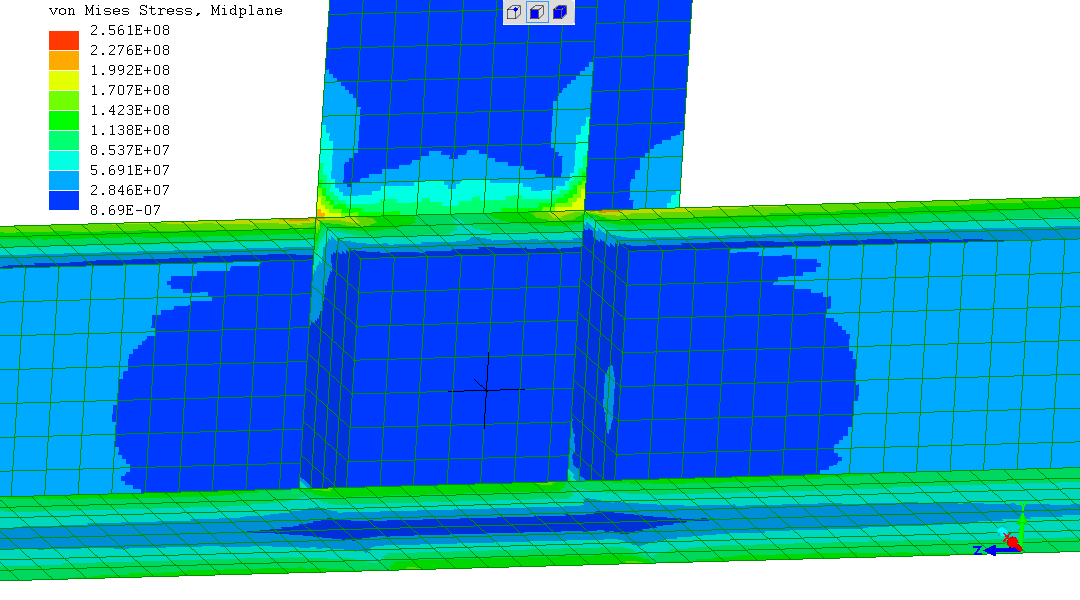
The highest general stresses of up to 170MPa, seen along the length of
the beam, are due to the moment ("torque") upon it. Produced by only
200kg-force upon the top of the 1m-tall column (2000Nm of moment
"twisting" the beam).
This stress is completely independent of the junction design.
This observation causes thought whether a more rigid section than an
I-beam, like a square box-section, is justified for the horizontal
member.
Large fillet weld sizes, in relation to the 8mm steel thickness, in vicinity of the "stress hotspots" in the "four corners" region of the column-to-beam junction, might dilute the forces across more load-path section and lower the four "hot-spot" stresses (?).
Refining a structure is a mix of what the customer wants and what is
evaluated in engineering terms as good enough for purpose. So I'll
back-out at this juncture, leaving you with this already much-improved
structure.
Assuming the Finite Element Analysis simulated design performs in real
life like the simulation. Which it has been established over a few
decades is generally the case...
(R. Smith, 27Sep2016, 28Sep2016)