This is a portfolio of my skills by which I can make this happen.
I'll jump ahead and answer the obvious question - how thin is thin? 6mm thickness is an approximate upper bound, as the steel gets too heavy for a person to easily person-handle and too stiff to flex it to enable assembly. Lower bound? Well, 3mm is a reasonable suggestion, as the steel is becoming too "springy" "sideways" with elastic buckling.
Three lines of experience
This class of structure is now economic in general steel fabrication company work due to the wider general effect of computational-power
The combination of
Typically now, a steel fabrications company buys-in the lasered-and-folded steel sub-components from a "profiler", whose machines automatically cut to the drawings received from its customer.
FEA now makes it economically feasible to predict the response of these 3-dimensional structures to the loads applied to them. Therefore to engineer them to serve the specified duty which the customer needs.
Applying "finite element" to this class of structures being discussed
gets a bonus which simplifies everything - the model can be comprised
of "shell elements" (look that up if you want to).
Very easy to form-up into a model of the component, and very
computationally economical.
At the time of writing in mid-2017, a model would have to be very
sophisticated to take as much as a minute to solve on a current
personal-computer.
This is about analysing the stresses, deflections, and possibly other characteristics, resulting from the service loads the product must bear.
The cycle of "redesign-and-reanalyse" until a design emerges which performs well and to customer specification is therefore much expedited.
Argon-rich shielding gases enable MIG to go into very "clean" spray-transfer, which makes possible welds which are both economical and have a high fatigue-life.
Applying "Trade" welding skills to weld with a high weldpool fluidity gives weldments with a high fatigue-resistance.
Poor fatigue-resistance performance of fillet-welds - the "tragic"
"Class F" performance (BS7608:1993) - has been almost universal but
was never mandatory.
Applying "ISO5817" without engineering overview had that systematic
effect. However, "ISO5817" correctly-applied certainly does "accept"
welds with a high fatigue-resistance.
What you do to obtain welds with high fatigue-resistance is to weld
with a high weld-pool fluidity.
Such a fillet-weld does not have "a perfect mitre" - it's a bit
curvaceous and tends to undulate along the length - and is "wetted-in
at the edges" which can trigger the zealous incorrect behaviour from
inspectors.
Independently, thin-plate "lasered" designs enable welds to be shifted
to low-stress regions (you know where these are from the FEA), and/or
the metal can be cut so that sub-components present long intersections
with long welds along which the forces are diluted to lower stresses.
Which is an additional means to get high fatigue-resistance from the
structure-in-entirety.
In assembling the thin-plate-metal component, you quickly become aware
than linear accuracy of the laser-cutting is much higher than the
angular accuracy of the press-braking (!).
That's understandable. The laser-cutting is solely about machine
accuracy. Whereas the folding (press-brake'ing) is about both the
machine accuracy (very accurate and determinate) and the material
property (very complex interaction of effects).
Result - you tend to be using lots of clamps, hydraulic jacks,
ratchet-straps, sash-cramps, etc, to "persuade" the
sub-components to "click-together" and line-up.
The outcome plenty justifies the effort :-)
Welding - I've mentioned this in my own pages . As I've said - measurement (Volts, Amps, etc) is good - especially in assisting the qualitative judgements you must make when setting-up welding processes!!!
Finite Element Analysis modelling...
This page on
Thin-plate shell-element FEA structural model
.
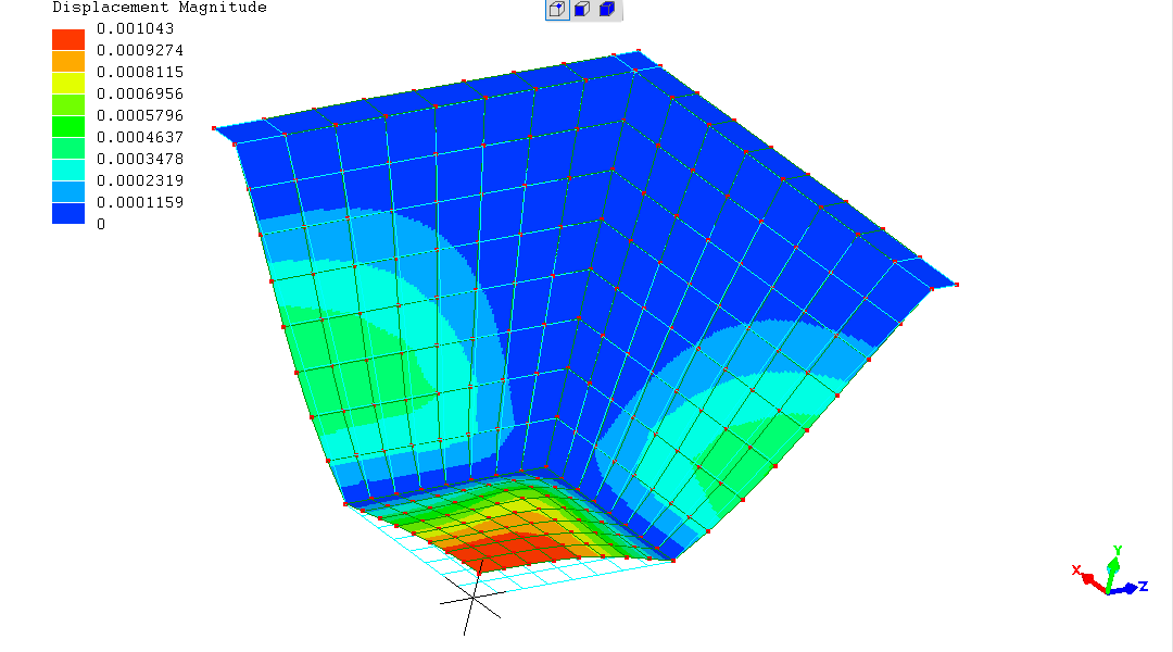
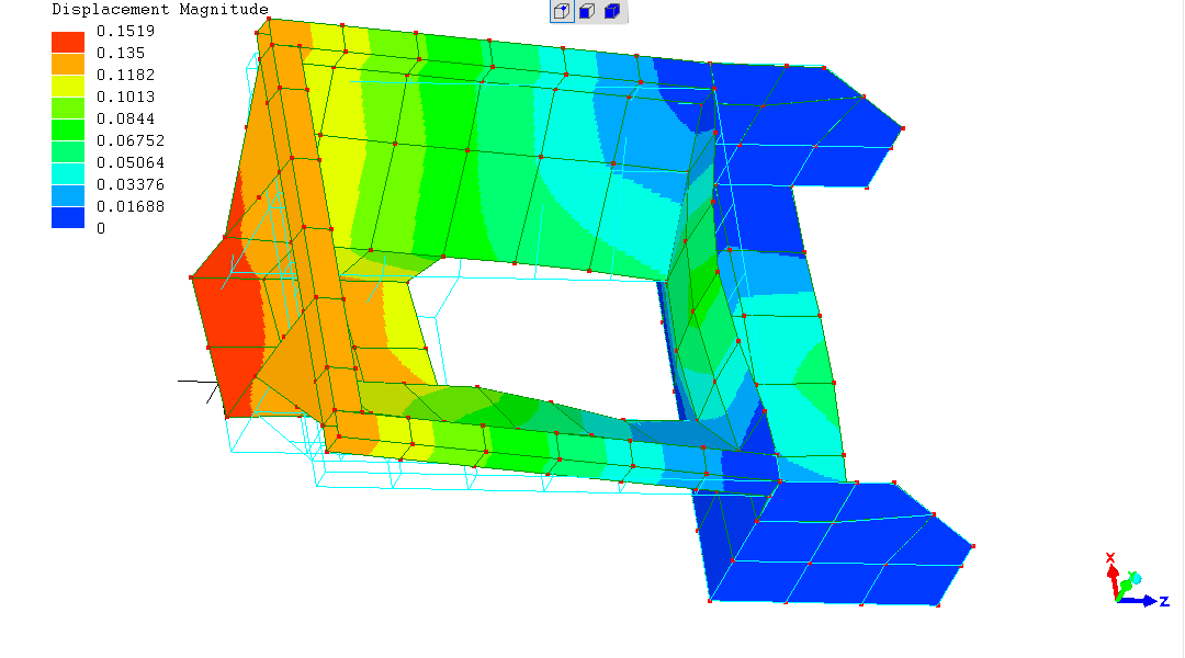
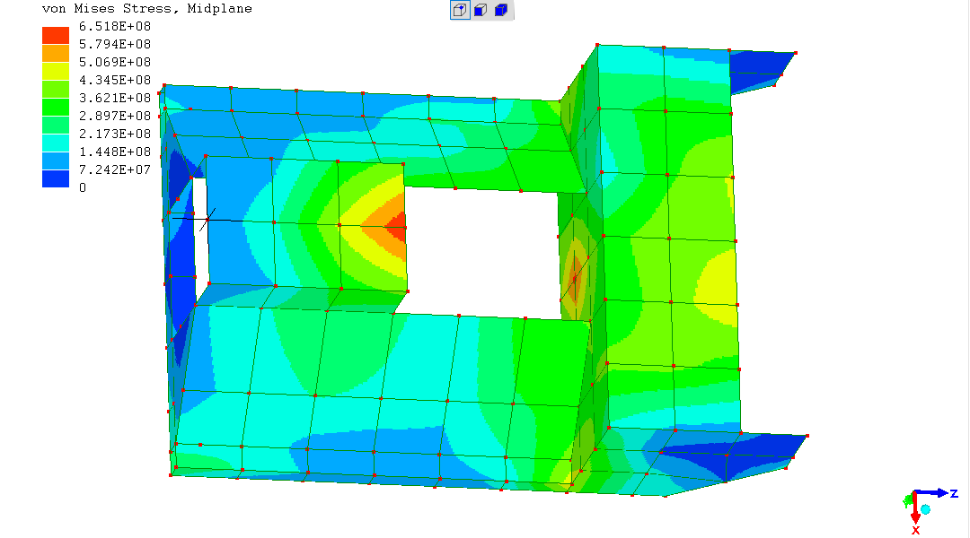
Some images of FEA model output...
One of the images from the FEA page for this very simple but completely effective component - a machine chassis for a pump, its associated control-valves and electronic, electrical and electro-mechanical systems.
Structural performance as lamentable as "Class F" fatigue-resistance :-)
It took less than a minute to reduce material thicknesses and re-run
the "solver" to produce this result. While pointedly ignoring the
need for stiffener gussets and/or stiffener panels...
(R. Smith, 01Jun2017, 30Jun2017)