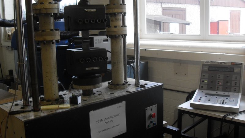
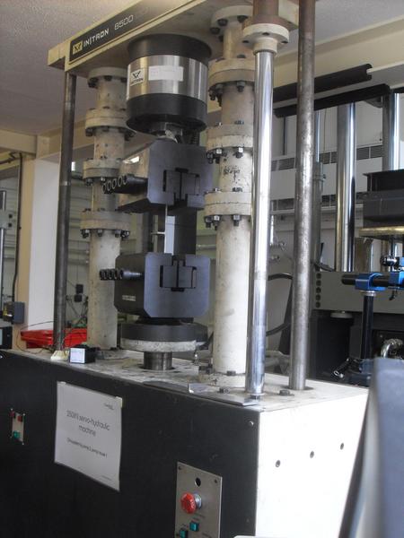
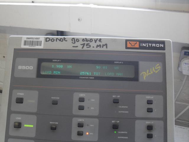
Last photo shows readout on fatigue testing machine controller
90kN is just over 9 Tonnes-force. These conditions are repeatedly stressing the sample to its nominal deformation yield stress and back down to a low near-zero stress (just enough to prevent slack and "rattle" in the system).
So this is a very severe test with the sample not expected to last long (if it did, we'd have invented a fabulous new welding method).
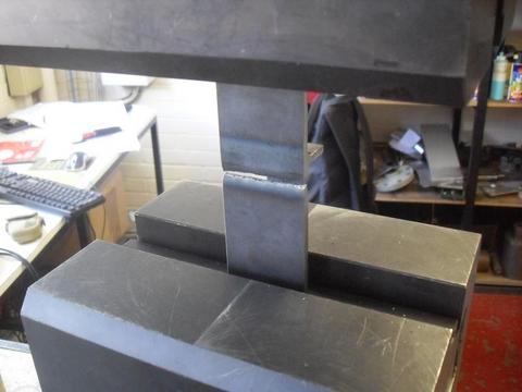
The elastic stretching and relaxing of the sample can be seen over a 150mm length marked with a permanent-marker when holding a rule against it. You get a good estimate of steel's Elastic Modulus (Young's modulus) from just this and knowing the max. load.
The sample broke at 46000 cycles.
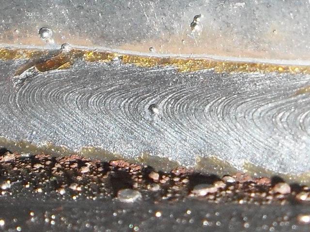
The fatigue crack appears to have initiated at the mid-width of the sample. It can be seen that greatest depth of fatigue crack is at the mid-width, whereas the crack becomes very shallow towards the sample edges.
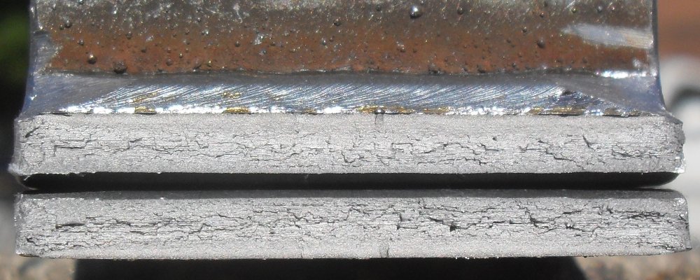
More comment on fatigue cracking behaviour is made considering the nominally identical second test sample.
All conditions for the second fatigue test were nominally identical to the first test. Except that the fatigue-testing machine cycled at 5Hz. Which is still a very low rate, not expected to change the outcome.
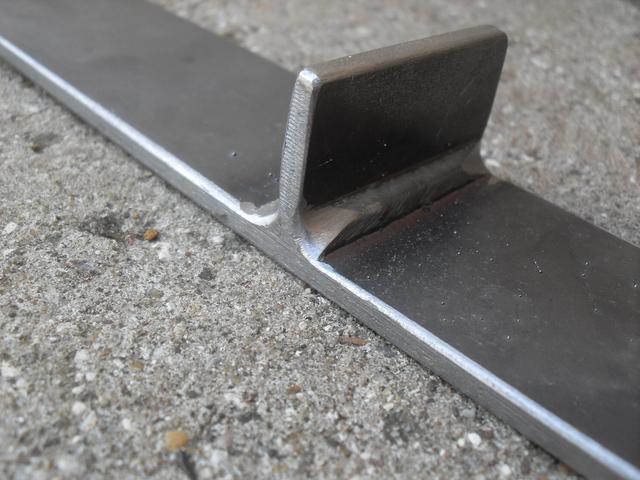
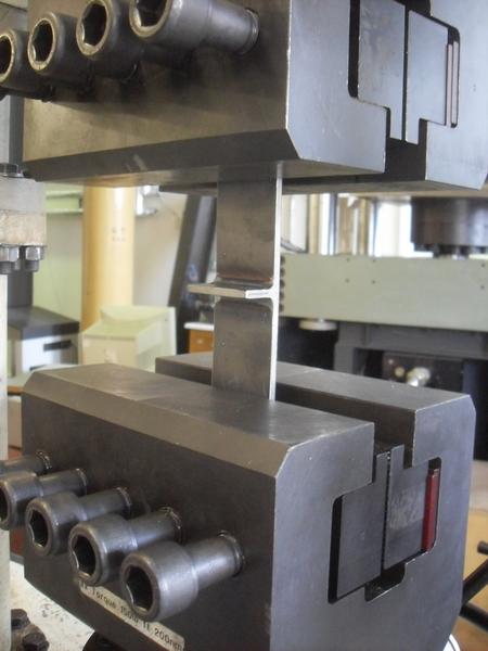
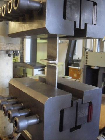
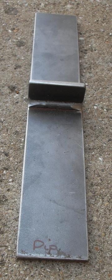
The sample before testing is as shown:
|
|
The smoothing of the weld profile at the sample edges can be seen. The aim is for fatigue cracking to initiate in the mid-width, rather than at the edges. A later otherwise identical test but with an unmodified simple cut through the weld, leaving sharp edges, also cracked in the midwidth. This could suggest the smoothing is unnecessary. On the other hand, one would have to prove that cracking did not start at the edges of the sample in a testing condition of low stresses and a large number of cycles - say 2million to failure.
Regardless, the desired behaviour of fatigue cracking at the mid-width was achieved.
The smoothing cannot have any proportional effect on the outcome. The exact form of edge-smoothing achieved is not an essential variable so long as it is part of an effective strategy of causing fatigue cracking to initiate in the mid-width of the sample. The physics of the mid-width fatigue cracking must then solely control the outcome.
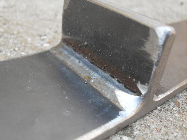
A white line is seen along one weld toe.
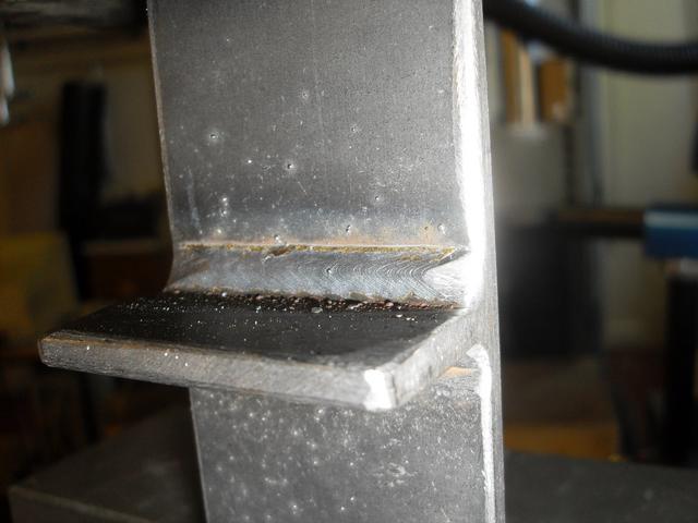
In sample 1 this seemed to correspond to a fatigue crack - as revealed on fracture. However, for the third sample, while watching an apparently similar white line, the sample broke on the opposite side!
The fatigue crack is at the more blended wider-angle weld toe, for both sample 1. Conventional logic indicates the sharper toe angle of the opposite weld should be the location where fatigue cracking initiates. No explanation for this unexpected result has yet been formulated.
gather all samples and make observations about crack location
Sample 2 was unbroken at 48330 cycles. It has been retained in this state for metallographic inspection.
R D Smith, 02 & 03 June 2011